After rebuilding the tonearm and drive carriage systems of this Beogram 4002 (5513), it was time to address the electronics. The first step is always to replace all electrolytic capacitors and RPM trimmers and relay to ensure trouble free operation in the decades to come. This shows the main PCB in its original condition:
And after replacing the components:
This shows the RPM control section in detail:
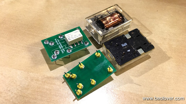
The replacement relay is a Beolover design that matches the footprint of the original Siemens relay:
These replacements re available to other enthusiasts. Just send me an email or use the contact form on the right. On to the reservoir capacitors. This shows the original dual capacitance unit:
This is a unique design containing two common grounded capacitors with 4700uF and 1000uF capacitances. These capacitors are not made anymore and so they need to be replaced with two individual units. To keep things organized, I designed a 3D printed fixture that holds things in place:
and from the back:
It fits precisely into the same spot and the original mounting clamp can be used to hold the assembly in place. This assembly is also available.
The final step was to replace the relay and single electrolytic capacitor on the output PCB. This shows the original board:
And with the replacement parts:
The red switch is an upgrade that I designed. It allows to connect system and signal grounds in case there are humming issues (mainly when connecting the Beogram to an amplifier with RCA inputs).


No comments:
Post a Comment
Comments and suggestions are welcome!