Featured Post

Beolover SyncDrive: DC Platter Motor Replacement for Beogram 4002 and 4004 (Type 551x and 552x)

Late Beogram 4002 and the 4004 (Types 551x and 552x), which have DC platter motors instead of the earlier synchronous AC motors usually suff...

Friday, July 21, 2017

Beogram 8000: Opening the Beogram to Service Position

I don't think Bang & Olufsen intended for the Beogram 8000 owners to ever open their turntable into its service position. The factory authorized service centers would take care of that. These days however, owners that want to do simple maintenance on their Beogram 800x model turntables must open their turntables up themselves. A common task like installing a new belt for the tangential arm drive requires putting the Beogram into service position.

For the technician though, the Beogram service position is great. It really isn't that difficult and like most things, having the correct tools makes a big difference.

The first step (not pictured) is lifting off the platter.
Next, there are some important Beogram 8000 components to be familiar with in opening up the turntable to its service position. For reference this picture points out the suspension lockdown screw. There are three lockdown screws and they must not be in the lockdown position to open up the Beogram. There are also three leaf springs and hangers that make up the floating suspension of the Beogram. The suspension hangs from the Beogram deck lid that needs to lift up so you must disconnect and lower the suspension before the Beogram can be opened.


I use a special hook tool that makes it pretty easy to grab the suspension hanger. Holding the leaf spring down with a thumb or finger allows me to lift the suspension hanger up and over the mounting hole of the leaf spring.


Another first step (you could do this step prior to lowering the suspension) is to remove a couple of plastic trim pieces inside the Beogram deck. For the piece covering the dust cover hinge mechanism I use a small, plastic pry bar tool like you find now days for working on cell phones and tablets. It can pry pieces that snap together open without marring the finish.


The other trim piece is the plastic cover over the tonearm and fixed arm.


Although the suspension is disconnected (and lowered) at this point the Beogram lid cannot open yet because of two screws under the left side of the chassis that lock the lid down.


It is kind of awkward to get to those as you can see. I hang the Beogram over the edge of the table a bit to get to them.

The Beogram lid can now start to lift into service position but there are still a couple of very important steps. The lid must carefully be maneuvered at the left edge where it is free from the chassis lip. Once it is free to tilt (lift) you have to make sure that the deck will clear the fixed arm of the Beogram.

When the Beogram deck is in its normal position for use, the distance between the edge of the deck and the fixed arm is not enough for the deck lid to open. It will surely clip the fixed arm (which would not be good).


By design the turntable floating deck, that the tangential arm assembly is a part of, can be slid to the right a little bit so there is clearance for the deck lid to tilt.

If you look at the posts in the pictures below the bottom picture shows the posts have been slid over to the right.


Now there is clearance between the deck and the fixed arm.


The deck lid now tilts up from left to right into the Beogram service position.


Now it is easy to change the tangential arm drive belt or whatever you need to get to inside the Beogram.


One extra note...Be very conscious of the dust cover lid and tonearm compartment lid with the Beogram deck tilted up. Sometimes I secure them with painter's tape to make sure they don't accidentally get damaged. For major work on the Beogram I remove the dust cover and tonearm compartment lids completely. However, you also have to be very careful in doing that as I have come across quite a few Beogram 800x units where the mounts for the dust cover have been damaged by people not careful with their removal. Perhaps that would be a good blog topic by itself.

Wednesday, July 19, 2017

Beogram 4004 Type 5526: Tangential Drive Work

The last post left off with the fixed arm sensor lamp being replaced with the custom Beolover lamp assembly. To go along with that (reversible) modification a change on the main board is also required.
Per Beolover's explanation here and his repair technique here I temporarily installed a 2M ohm trimmer resistor on the trace side of the main board so I can easily make the initial adjustment. I will do that adjustment later when I get ready to test these current changes.

This picture shows the original 1M ohm resistor (R26) that will get replaced.


Here is the replacement 2M ohm trimmer installed in its temporary location until the adjustment procedure can be made.


As I moved on to install the Beolover replacement module for the tangential tracking I noticed something wrong with the arm lowering solenoid. I didn't notice the problem when I was busy working on the damper but here in this picture you can clearly see that the solenoid is missing its plunger.

I found the plunger and re-attached it to the lever using a dab of lock-tight.


To fix the solenoid I removed all of the arm damping components again and will leave them out while I work on the rest of the tangential arm assembly. Having the chassis clear of those components will make working in there a little easier.

Here is the removal of the original tracking sensor assembly. The Beolover replacement part will fit right in place of the original light source housing and the original parts will be saved in case someone wants to revert back to them in the future.


That looks great. Now on to the drive screw cleaning and lubricating.
The drive screw bearing nut and housing always gets dirty over time. This one is no exception. There are even some specs of debris from the disintegrated chassis lock down bushings. Those pieces continue to show up.


I completely remove the drive screw and parts for cleaning and re-lubricating.


I am satisfied the drive screw parts are clean and ready for re-assembly.
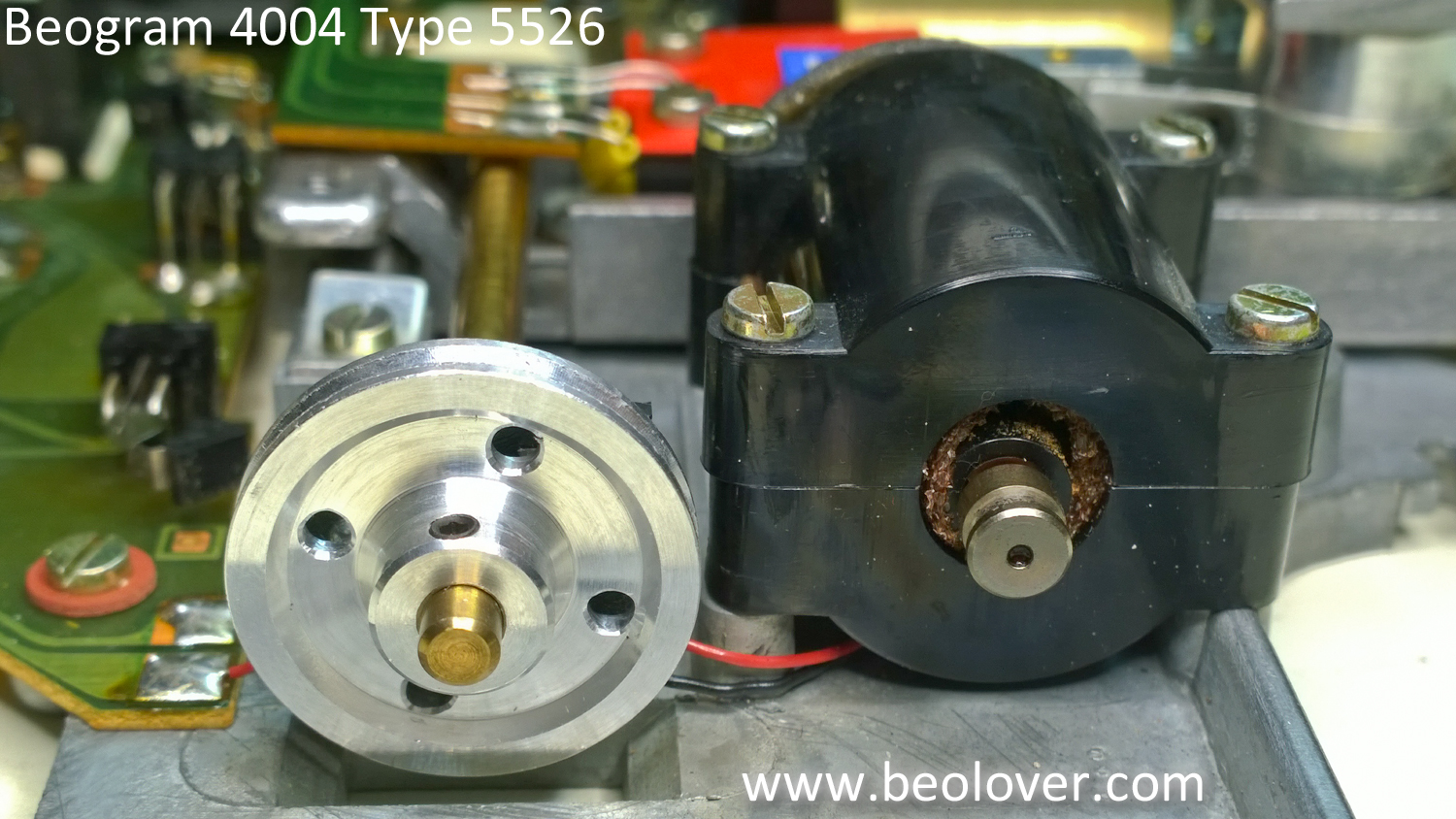
This is the point in the restoration where I also replace the tangential drive pulley. This picture shows the pulley options.  I like to replace these Beogram 400x drive pulleys with aluminum replacements from Nick (contact us if you want to get in touch with him).

The aluminum pulley on the left is Nick's original replacement (version 1). The black plastic pulley on the right is the original Beogram 4004 pulley. The pulley I am currently going with is Nick's Version 2 aluminum pulley (the one in the center of the picture). It is a nicer reproduction of the original pulley and is lighter weight than the Version 1 pulley. The indention of the middle area of the pulley also prevents accidental contact with the drive screw mounting bracket screws. A really super nice upgrade.


Here is the drive screw re-assembled with the new pulley.


I will go ahead and note it here that the tangential drive motor on this unit seems a little loose in its housing. I will look at that more closely when I get the Beogram put back together for testing. If I have to I will change out that motor.

Next I put the arm lowering parts back in place. The solenoid plunger is where it should be now.


I made one more electrical change on this Beogram tangential drive assembly while I had it out of the box. Like the recent Beogram 4002 restoration I changed out the old light source for the arm position sensor. The new LED light source will insure there won't be any problems with the old light source failing later. I also took the opportunity to clean the contacts of the tangential arm position switches (shown by the red arrows).


That pretty much does it for the tangential drive electrical restorations. All that I need to do before re-assembling these parts for testing is to align and balance the tonearm.

Monday, July 17, 2017

Beogram 4004 Type 5526: Fixed Arm Work

This Beogram 4004 restoration is going to include changing out the fixed arm record sensor lamp with a Beolover LED replacement part. Since this operation is easiest with the fixed arm unbolted it is also an opportunity to clean and lubricate the pivot point of the tonearm lift/drop lever.


The fixed arm sensor lamp assembly is usually securely mounted in the end of the arm. It takes a firm grip and careful pressure to work the black plastic assembly out of the arm. That is why it is best done with the fixed arm unbolted.


Here is the Beolover replacement sensor lamp (LED). It is a special, flexible printed circuit board with surface mount components to replicate the original sensor lamp. The nice thing about it is there is no guess work in positioning the lamp for the lens. The Beolover part is shaped so it only fits one way and that way perfectly positions the new LED lamp over the lens.


After mounting the new sensor lamp and fishing the lead wires through it is a simple clamp, solder and trim operation to complete the installation.


Saturday, July 15, 2017

Beogram 4004 Type 5526: Tonearm Lowering Damping

The tonearm lowering on the Beogram 400x turntables is accomplished by a solenoid that engages/disengages per an electrical control signal. When the solenoid engages, the tonearm is free to lower. To prevent a straight drop of the stylus onto the record there is a damping piston that slowly lowers the tonearm.

On these Beogram 400x turntable restorations we always service the arm lowering mechanics to make sure it is operating correctly and continues to operate correctly.

This picture shows the arm lowering components before I worked on them.


There are just four screws to remove and two springs to detach in order for the arm lowering damper to be removed for service.


There you have it. The Beogram 4004 arm lowering mechanics removed for servicing.


The damping piston valve control is opened up (I remove it) and the piston pulled out of the tube.


Everything is wiped down then lubricated again before re-assembly.

Here are the lowering components re-installed. Pulling on the solenoid engage lever manually allows me to check the piston control valve and adjust it so the tonearm lowers to play position in about one second.


While the tangential arm components are removed from the chassis I will do more cleaning and lubricating. I will also change out the stationary arm lamp and sensor with the custom Beolover replacement part.

Before I get to that though, I was not completely happy with the installation of the optional phono grounding switch on the output board. A nice thing about having pictures to document a restoration is that I can review them and evaluate the results of my work.

On this Beogram 4004 output board I felt the need to use hot glue to secure the optional grounding switch. Without something to secure it the switch was wobbly. The 1M ohm trimmer resistor on the board takes up too much space to allow me room to install the switch the way I would like.


You can see the glue doing its job in the above pictures. Not horrible but I don't like the look.
I decided to go back and rework this installation. I changed out the 1M ohm trimmer resistor with one that has a smaller footprint (setting the resistance value to what the original setting was).

The new trimmer resister gave me enough space to install the switch better so that I don't need any hot glue. As you can see below the black hot glue peeled right off and is gone now. I like this version of the installation much better.


Thursday, July 13, 2017

Beogram 8000: Returning Home

Today is the big day. It is time to pack up the Beogram 8000 and ship it home to its owner. The turntable has been playing beautifully the last few days with very heavy use and no signs of any intermittent behavior. It was definitely a good thing to install a brand new phono muting relay.

After all of that work it is important to properly pack units up for shipping. Especially turntables. A loose item here or there can cause extreme damage. Everything must be locked down and secure.

Bang & Olufsen has long been using a floating chassis for their turntables and provide a chassis lock down mechanism for transporting them. On the Beogram 8000 (and 8002) there are three lock down bolts under the main platter. The bolts are screwed down out of the way when the turntable is ready to be used. For transport the bolts are backed out and through a mounting plate. When through a hole in the mounting plate, the plate is slid over and the bolt is tightened against it so the floating chassis cannot move.


This lock down should be performed even if transporting the turntable in your vehicle to deliver it yourself.

The phono cartridge should also be removed from the tonearm at this point. To secure the tangential arm assembly and the top platter, B&O provided a special molded styro-foam piece. It holds the top platter securely and slides onto the deck of the Beogram with a tab to block the tangential arm assembly from moving.


The dust cover lowers on top of the platter packing to protect the dust cover and to hold the platter down so the sub-platter cannot move.


The outside of the Beogram is then protected with a soft, foam sleeve.


Finally, two molded styro-foam blocks slide over the front and back of the Beogram to lock all of the packing in place.


The Beogram and shipping material is placed into its original box which is inside an outer box that has thick foam protection on all sides.


It costs more of course but please don't ever skimp and not use an outer box. That is just asking for trouble. The only time to use just the original box by itself is if you are hand delivering the unit.

The final step is sealing the shipment and applying the shipping label. Then off it goes.


Beogram 4004 Type 5526: Output Board Recap and Update

The Beogram 4004 output board has the usual phono signal connector and muting relay but also has circuitry added to allow remote control functionality from a Beomaster such as the Beomaster 2400. For this board I replaced the two electrolytic capacitors with new ones and the two tantalum capacitors with WIMA MKS capacitors. I replaced the muting relay with a new, sealed Omron relay mounted on Beolover's custom adapter (so that it is directly replaceable with the original National relay).


As Beolover typically does I added an optional phono cable grounding switch to the output connector. This switch allows an owner to connect the phono signal shield wires to the Beogram chassis ground or leave them open (as they normally are). The normal configuration is fine when using the Beogram phono DIN connector with a B&O Beomaster (like the 2400). However, when connecting the phono cable to a non-B&O amplifier there is often hum present that requires connecting an extra grounding wire from the Beogram to the amplifier chassis ground lug. This grounding switch eliminates the need for the extra grounding wire.

While the small switch is secured by the leads soldered to the board, I added black hot glue around it to give it extra support. I like that glue for this application because it will provide the needed support but isn't permanent like epoxy glue. The black hot glue can be peeled off in the future if so desired.


This board is a quick task so it is on to turntable mechanical parts for cleaning, lubrication and adjustment.