There is just barely enough time to get in one more vintage Bang & Olufsen restoration project for 2019.
This is another Beomaster 2400 restoration. I have had quite a few Beomaster 1900 and 2400 projects this year so why not another one.
Let's jump right in and evaluate the starting condition of this Beomaster.
Cosmetically it looks very nice.
Since it is in such nice shape I decided to power this unit up and see what its status is with regard to lights and touch control switches.
I was pleasantly surprised that all of the touch switches work and most of the lights do as well. The Treble indicator light is burned out apparently.
Now on to opening the Beomaster 2400 cabinet up to get to the circuit boards inside.
For this restoration project I will be doing the usual replacement of electrolytic & tantalum capacitors, the cleaning of the slider switches and any other repairs I run into as I check out the insides of this receiver.
First I remove the door and panel for the tone controls and FM channel tuning.
Second is the removal of the Beomaster 2400 bottom plate.
Note that the Phono DIN plug is the 7-pin type. That means this Beomaster has (or supports) the circuitry for (wired) remote control of a Beogram 4004.
That is desirable in this case because the owner has a fully restored Beogram 4004 ready to use with this receiver.
Now for the removal of the touch control panel.
The bass, treble and balance controls have indicator masks that are in excellent condition. I will have to look closer but all three slider controls appear to be fully intact.
This version of a Beomaster 2400 has different and newer board to board connectors.
Here is the main body of the Beomaster 2400 after I have removed all of the other components.
I don't like trying to de-solder and solder electrical components in between the frame pieces of the cabinet. I prefer to remove boards and components from a unit and work on them individually.
This Beomaster 2400 is now broken down to where I can start recapping the main board.
I like to start with the most difficult task first and get it out of the way.
Featured Post
Beolover SyncDrive: DC Platter Motor Replacement for Beogram 4002 and 4004 (Type 551x and 552x)
Late Beogram 4002 and the 4004 (Types 551x and 552x), which have DC platter motors instead of the earlier synchronous AC motors usually suff...
Showing posts with label how to open. Show all posts
Sunday, December 15, 2019
Tuesday, August 6, 2019
Beomaster 8000 - How to open into service position
For the DIY Beomaster 8000 owners out there here are some visual instructions on how to open up a Beomaster 8000 into its service position. This is useful when an owner wants to inspect and measure some internal component or if a board needs removing for replacement.
First...here are some instructional diagrams to open the Beomaster 8000 from the service manual.
NOTE: Do this with the Beomaster 8000 power cord unplugged.
First...here are some instructional diagrams to open the Beomaster 8000 from the service manual.
NOTE: Do this with the Beomaster 8000 power cord unplugged.
Here are corresponding photos of what those actually look like.
NOTE: Many Beomaster 8000 units do not have the complete set of the three flat, metal springs.
Those springs just lay in place so often fall out when someone carelessly opens up the
Beomaster. As a result the springs get lost. Always have a small plastic box or bag to
put the removed parts.
After the springs are carefully removed and stored there are some retaining screws that secure the front panel of the Beomaster to the chassis.
With the panel securing screws removed the front panel can slide forward and lifted up to its service position. There are three brackets the were holding the front edge of the panel to the Beomaster chassis. Those brackets are now used to set the panel upright on the front edge of the frame.
Next is the smoked glass cover over the Beomaster 8000 displays. To remove that assembly there is a black plastic trim piece that must be removed.
Under the trim piece are three more screws. Those three screws only need to be loosened in order to slide and lift the glass panel out.
The Beomaster 8000 display board is not revealed. At the top of the display board are two securing screws. Those need to be removed to put the Display board and Microcomputer board into their service position.
NOTE: It is not uncommon for one or both display board tabs (B & F in the photo) to be broken
from mishandling.
The Display board is connected to the Microcomputer board which connects to the Beomaster 8000 chassis by a pivoting hinge. Together, via the hinge, both the Microcomputer board and the Display board can be tilted up into the service position. A slot in each hinge locks the assemblies in place.
Now the Beomaster 8000 Power Supply board and Right Channel Output Amplifier board are visible and accessible.
Next is the left side of the Beomaster 8000. There is one screw remaining where the release bar was removed. This screw is holding the Filter and Tone Control panel in place.
Once that screw is removed the Filter and Tone Control board and panel assembly can be tilted up into its service position. Unfortunately Bang & Olufsen did not provide a built in mechanism to hold this assembly in the service position. I carefully place a small screw driver to hold the panel open.
At this point all of the Beomaster 8000 boards can be accessed.
Full access and removal of the left and right Output Amplifier assemblies involves more disassembly steps from this point. Those steps will be added to the blog in the near future. This post focuses on opening up the Beomaster 8000 to its basic service manual position.
TIP: If you want to remove one or more of the now accessible boards from the open Beomaster, keep
in mind there are quite a few cable connections involved in the removal process. It is always
good to take plenty of pictures but I recommend using a black Sharpie type felt marker to label
all of the connectors. Even though I have disassembled a lot of these amplifiers I still label the
connectors to make reassembly easy.
Monday, July 1, 2019
Beomaster 2400 Type 2902: Another restoration project begins
An owner of a Beomaster 8000 restoration I did last year sent me a nice Beomaster 2400 unit that needs some work. Today I was finally able to put it on the bench and check out what condition it was in.
The outside cosmetic condition of this Beomaster 2400 is quite nice. With it plugged in I can get sound from the FM tuner testing the Beomaster output with some headphones. I can see however that the Treble indicator lamp is burned out. In addition, the Bass and Treble controls do not work. The slide control knobs are loose which is a symptom of broken sliders.
As you can see, a handsome Beomaster 2400 unit. It didn't arrive with a remote control so I used mine to check that the remote control functionality works...it does.
Now it is time to open the Beomaster up. I know that it partially works so that is good. However, the problems it shows from the initial testing indicate that typical problems for this receiver exist.
The disassembly begins by removing screws on the underside of the Beomaster. I have circled the screws that I remove with red circles in the pictures.
This is an early production Beomaster 2400 unit. The Phono DIN jack is the 5-pin type of DIN jack. Later Beomaster 2400 units were fitted with 7-pin DIN jacks to go along with the added support of remote control functionality of the Beogram 4004 turntable. Bang & Olufsen produced a modification kit that included a 7-pin DIN jack and wires to add the Beogram 4004 remote control support to these early models.
Here is the schematic diagram from that mod kit.
We will decide later in this restoration whether this mod kit will be applied. Interestingly, there are 7-pin DIN jacks available for the Beomaster 2400 from later model Beomaster 1900 units. Because the Beomaster 1900 and 2400 share the same main board Bang & Olufsen started installing 7-pin DIN jacks on both the Beomaster 2400 and the Beomaster 1900 units...even though the BM1900 receivers do not have remote control circuitry. Swapping a 5-pin DIN jack from an early Beomaster 2400 with a 7-pin DIN jack from a later model Beomaster 1900 would not result in loss of functionality for either unit.
Continuing on with the Beomaster 2400 disassembly I loosened the rear panel for removal.
That step allows the bottom panel that was loosened earlier to now be removed.
Next is the removal of the tone control and FM tuning control panel. Two screws are removed on either end of the panel to allow it to slide out.
Now for removal of the bottom control panel (volume control and source selection).
With the control panels removed I can see the inside components of the Beomaster 2400. I spot some problems with the Bass and Treble tone controls as well as with the display indicator masks for Bass, Treble and Balance.
The indicator masks have started to deteriorate from the heat produced by the indicator lamps. I have seen this before on the Beomaster 1900 (which as I said before, is essentially the same receiver...minus remote control).
I have new replacement masks I can fix the deteriorating ones with. In this restoration I will also change the Bass, Treble and Balance display lamps to LED lamps which run way cooler and should not repeat this problem.
Be careful removing the little brass clips that hold the display mask to the slider bridge. If done wrong the lip of the brass clip can easily be broken off. The ends of the clips need to be pressed inward then up as shown here.
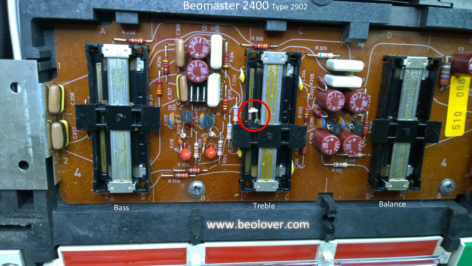
The Bass and Treble adjustment sliders are loose and do not function. This is usually because small, plastic clips on the plastic slider bridges have failed. I can see that is the case here. Martin Olsen produces replacement bridge parts to fix this problem so I will be installing those here.
To continue the disassembly of the Beomaster 2400 I need to loosen and remove the tone control and tuner control board followed by the removal of the three indicator lamp modules (volume, tone control and source selection).
Now all that is left is to loosen the large, main board so I will be able to get to the majority of capacitors that need replacing in this restoration project.
The FM tuner box (the shiny silver box) and the FM antenna jack must also be loosened.
Finally the main board can be lifted up for access to all of its components.
I can also get to the two reservoir capacitors easily now for replacement of those.
The initial evaluation is complete on this unit and the Beomaster 2400 is opened up where restoration work can begin.
The outside cosmetic condition of this Beomaster 2400 is quite nice. With it plugged in I can get sound from the FM tuner testing the Beomaster output with some headphones. I can see however that the Treble indicator lamp is burned out. In addition, the Bass and Treble controls do not work. The slide control knobs are loose which is a symptom of broken sliders.
As you can see, a handsome Beomaster 2400 unit. It didn't arrive with a remote control so I used mine to check that the remote control functionality works...it does.
Now it is time to open the Beomaster up. I know that it partially works so that is good. However, the problems it shows from the initial testing indicate that typical problems for this receiver exist.
The disassembly begins by removing screws on the underside of the Beomaster. I have circled the screws that I remove with red circles in the pictures.
This is an early production Beomaster 2400 unit. The Phono DIN jack is the 5-pin type of DIN jack. Later Beomaster 2400 units were fitted with 7-pin DIN jacks to go along with the added support of remote control functionality of the Beogram 4004 turntable. Bang & Olufsen produced a modification kit that included a 7-pin DIN jack and wires to add the Beogram 4004 remote control support to these early models.
Here is the schematic diagram from that mod kit.
We will decide later in this restoration whether this mod kit will be applied. Interestingly, there are 7-pin DIN jacks available for the Beomaster 2400 from later model Beomaster 1900 units. Because the Beomaster 1900 and 2400 share the same main board Bang & Olufsen started installing 7-pin DIN jacks on both the Beomaster 2400 and the Beomaster 1900 units...even though the BM1900 receivers do not have remote control circuitry. Swapping a 5-pin DIN jack from an early Beomaster 2400 with a 7-pin DIN jack from a later model Beomaster 1900 would not result in loss of functionality for either unit.
Continuing on with the Beomaster 2400 disassembly I loosened the rear panel for removal.
That step allows the bottom panel that was loosened earlier to now be removed.
Next is the removal of the tone control and FM tuning control panel. Two screws are removed on either end of the panel to allow it to slide out.
Now for removal of the bottom control panel (volume control and source selection).
With the control panels removed I can see the inside components of the Beomaster 2400. I spot some problems with the Bass and Treble tone controls as well as with the display indicator masks for Bass, Treble and Balance.
The indicator masks have started to deteriorate from the heat produced by the indicator lamps. I have seen this before on the Beomaster 1900 (which as I said before, is essentially the same receiver...minus remote control).
I have new replacement masks I can fix the deteriorating ones with. In this restoration I will also change the Bass, Treble and Balance display lamps to LED lamps which run way cooler and should not repeat this problem.
Be careful removing the little brass clips that hold the display mask to the slider bridge. If done wrong the lip of the brass clip can easily be broken off. The ends of the clips need to be pressed inward then up as shown here.
The Bass and Treble adjustment sliders are loose and do not function. This is usually because small, plastic clips on the plastic slider bridges have failed. I can see that is the case here. Martin Olsen produces replacement bridge parts to fix this problem so I will be installing those here.
To continue the disassembly of the Beomaster 2400 I need to loosen and remove the tone control and tuner control board followed by the removal of the three indicator lamp modules (volume, tone control and source selection).
Now all that is left is to loosen the large, main board so I will be able to get to the majority of capacitors that need replacing in this restoration project.
The FM tuner box (the shiny silver box) and the FM antenna jack must also be loosened.
Finally the main board can be lifted up for access to all of its components.
I can also get to the two reservoir capacitors easily now for replacement of those.
The initial evaluation is complete on this unit and the Beomaster 2400 is opened up where restoration work can begin.
Subscribe to:
Posts (Atom)