Featured Post

Beolover SyncDrive: DC Platter Motor Replacement for Beogram 4002 and 4004 (Type 551x and 552x)

Late Beogram 4002 and the 4004 (Types 551x and 552x), which have DC platter motors instead of the earlier synchronous AC motors usually suff...

Showing posts with label leaf spring. Show all posts

Monday, May 24, 2021

Beogram 8002 From North Carolina: Dust Cover Repair Part 2...ongoing saga

My feeling of enjoyment after the Beogram 8002 dust cover repair (in the previous post) was short lived.

As I spent time adjusting the dust cover lid damping tension and exercising the dust cover, as with typical use, I started to notice that the little bump in the dust cover from the original problem was becoming a problem again.

I had been a little worried about whether the epoxy repair would hold up.  The original problem was that the dust cover hinge assembly was bent upward at the point the lid damping fixed hinge mounts to the back part of the dust cover. 

In hindsight I should have completely disassembled the dust cover lid and examined the back part more closely.  

Performing some careful removal of my epoxy work I was able to successfully disassemble the Beogram 8002 dust cover assembly.

Sure enough...I discovered that the over stressing of the dust cover damping spring on the fixed hinge, in concert with the fact that the back part of the dust cover was not properly attached to the cabinet, resulted in a cracked joint on a crucial hinge attachment.


That break point isn't in a location where epoxy on the joint, by itself, can hold up to the damping spring force on the fixed hinge. 

The best solution in this case is to get a replacement for the broken dust cover back part.  Fortunately I have such a replacement in my parts archive.

Here is a side by side look at the broken back part and the replacement.  


Looking at the two parts side by side I noticed that the location where the fixed hinge mounts to the back part hinge bar has a broken tab on the faulty back part.


Here is the back of the Beogram 8002 cabinet with the dust cover components removed (again).


Here are the dust cover assembly and tonearm compartment lid components disassembled.


Another problem I had noticed with this Beogram 8002 cabinet was that the deck trim and tonearm compartment lid did not seem to be securely in place. 

I pulled off the deck trim piece and separated the tonearm compartment lid from its hinge plate.


You can see that whoever worked on this Beogram 8002 before me did not bother to remove the old, original B&O mounting tape residue. They just added more tape.

I will reset everything and start with clean surfaces.
The first step was to soak the old tape residue in some GooGone for a few hours.


Once the GooGone had done its job I was able to scrape off the old tape residue and wipe the surfaces clean in preparation for reattachment of the parts.


Everything now looks clean and proper for reassembly.  That will have to wait until the next post :-)

Wednesday, May 19, 2021

Beogram 8002 From North Carolina: Repairing a particularly troublesome dust cover

When this project began and I was doing the initial assessment I noted that the dust cover mechanics were not working properly.  A Beogram 8002 dust cover mechanical problem is not rare. I have often mentioned that it isn't one of my favorite Bang & Olufsen engineering decisions. While the design is the expected elegant and simple design, its components don't hold up all that well.

The dust cover mechanism on the Beogram 8002 is the same design as the Beogram 8000.  The leaf spring for the damping of the dust cover hinge differs in shape sometimes but the mechanics are the same.

Looking at the Beogram 8002 dust cover hinge design here are the main mechanical parts...
These first two photos are from other Beogram 8002 turntable restorations I have done but they are good to post again in showing the hinge assembly.


The operation of the hinge is supposed to work where the fixed bracket, shown mounted to the plexiglass dust cover lid, mates with the pivoting bracket.  The pivoting bracket mates with the leaf spring that has an adjustable tension (via a set screw).  The tension dampens the lowering of the dust cover lid and provides just enough force to keep the lid open.


In order for the hinge mechanism to function properly the dust cover lid must mate tightly to the back of the Beogram 8002 cabinet.  The fixed bracket on the plexiglass lid must also fit tightly against the lid and not move.

A common cause of a Beogram 8002 lid mechanism failing is that the fixed hinge piece comes loose.
Unfortunately, just like the Beogram 8002 deck panel and tonearm cover lid, Bang & Olufsen used a foam type double-sided tape to secure the pieces. That tape eventually deteriorates to the point where it no longer secures what it is attached to...and the pieces separate.

That is what happened at some point with the Beogram 8002 of this project. 

Further problems developed when some previous technician who was not familiar with Beogram 800x turntables made poor decisions in attempting to repair the dust cover mechanism.

Here are some photos again of this project's Beogram 8002 dust cover hinge.
You can see by the lines I marked on the photo in red that the fixed hinge piece separated from the dust cover lid. 


During whatever sequence of repair attempt events, the previous work on the dust cover involved some hot glue and some force that bent part of the Beogram 8002 dust cover lid mechanism.


What this failed repair attempt did was secure the dust cover enough where it was in place on the cabinet but there was way too much tension on the leaf spring where it forced the moving hinge bracket so hard against the fixed bracket that it bent the long, piano type, bar hinge.  Another contributor to this problem was that the back of the Beogram cabinet and back of the dust cover hinge were not secure.  The dust cover top was forced up and beyond where it should ever be leaving a bulge in the lid.

I have to say I have never seen a Beogram 800x dust cover hinge improperly adjusted this badly.

The person should have noticed that the leaf spring tension was too much and was forcing the whole dust cover assembly upward from the frame.

Too late for that now. 

One lucky thing was that their poor attempt at repairing the problem with glue resulted in deciding to use hot glue. Not good for permanent glue repairs but a good thing here because the hot glue was easily removed.

Now for the repair of this mess and yes, this dust cover assembly is worth saving.
Surprisingly, in spite of what it has gone through, this dust cover assembly is in excellent condition.

The first step was to remove the dust cover assembly (with the tonearm compartment lid).
With the dust cover laying flat upside down I cleaned off the old adhesive material and glued the fixed hinge bracket in place using epoxy.  I let that cure for twenty-four hours.


Back on the Beogram 8002 cabinet where the leaf spring and moving hinge bracket live I examined the spring compartment from the back.  There is a teflon or teflon-like material where the smooth plastic edge of the leaf spring's plastic guide slides during operation of the hinge.

The teflon strip of material needs a bit of realigning so that became part of the repair task.


When testing the fit and adjustment ability of the leaf spring and its tension set screw I discovered the fit was not so good and the metal sleeve for the set screw was loose.


I wanted to make sure that the set screw sleeve didn't have any play in it so I epoxied the under side end of the sleeve to the cabinet frame.  Now only the set screw is the piece that will move.


On the inside cabinet wall, where the plastic guide piece slides along during operation of the hinge, I removed the teflon strip of material.  I epoxied in place a strip of Dura-Lar then put the original teflon strip on top of that.

A test fit of the leaf spring and moving hinge bracket assembly showed that everything on this part of the mechanism is back in good working order.


Regardless of how traumatized a Beogram 800x dust cover hinge mechanism is an important thing to remember is that the back part of the dust cover lid (the long, thin flap of plastic) must fit tightly against the back wall of the Beogram cabinet.

These photos attempt to show how the dust cover flap is supposed to mate with the back of the cabinet.


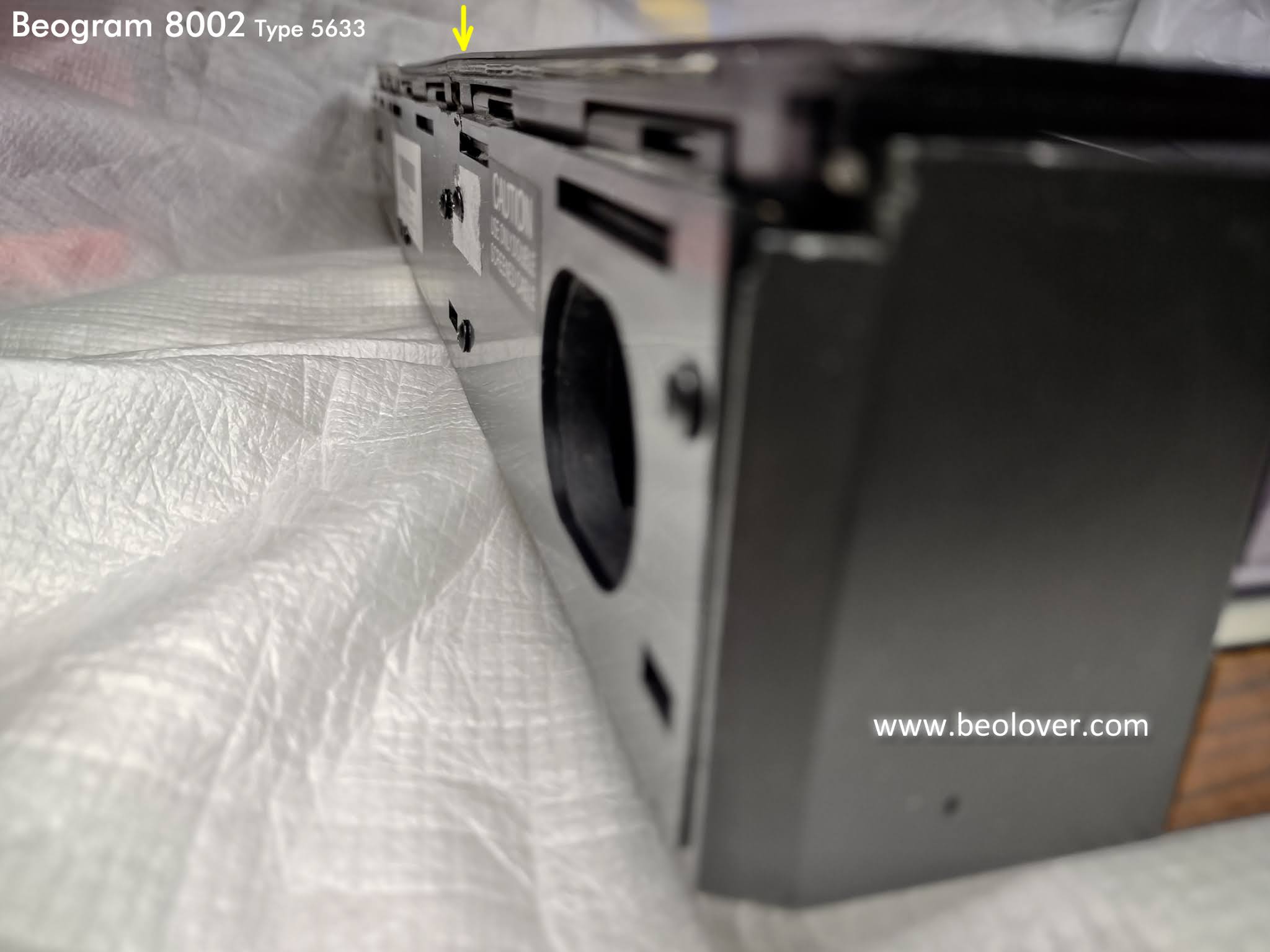
This photo shows the back of the Beogram 8002 cabinet and how the back flap of the dust cover assembly should be flat against the cabinet rear wall.

There was one added screw in the back of the Beogram to help secure the dust cover assembly to the cabinet but as shown earlier, it was not sufficient to prevent the tension in the leaf spring from bending the dust cover upwards at the hinge mount.


I actually went through a few iterations of fitting the dust cover onto the rear wall of the cabinet.
I tried some additional mounting screws and while they helped a little I realized that the only real option I had was to epoxy the dust cover assembly and cabinet frame together.  The added screws would be useful in pulling the pieces together while the epoxy cured.


I also had to make sure there was some epoxy around the dust cover to cabinet mount points where the dust cover hinge had bent.  At the same time, I had to be careful no epoxy got on any parts that are supposed to move.  With the epoxy curing for twenty-four hours and the dust cover clamped tightly to the cabinet frame I hoped that would result in a solid working dust cover hinge.


Looking carefully I can tell there is a very slight bend in the line of the dust cover hinge but it is very minimal now.  I think this is as good as I can get it. The slight bend in the back is not noticeable from the front of Beogram 8002 and it doesn't increase with the movement of the dust cover like it did before the fix.


I just need to add some damping grease to the tonearm compartment lid hinge and I will be ready to put the Beogram 8002 turntable components back into this cabinet.


Friday, July 21, 2017

Beogram 8000: Opening the Beogram to Service Position

I don't think Bang & Olufsen intended for the Beogram 8000 owners to ever open their turntable into its service position. The factory authorized service centers would take care of that. These days however, owners that want to do simple maintenance on their Beogram 800x model turntables must open their turntables up themselves. A common task like installing a new belt for the tangential arm drive requires putting the Beogram into service position.

For the technician though, the Beogram service position is great. It really isn't that difficult and like most things, having the correct tools makes a big difference.

The first step (not pictured) is lifting off the platter.
Next, there are some important Beogram 8000 components to be familiar with in opening up the turntable to its service position. For reference this picture points out the suspension lockdown screw. There are three lockdown screws and they must not be in the lockdown position to open up the Beogram. There are also three leaf springs and hangers that make up the floating suspension of the Beogram. The suspension hangs from the Beogram deck lid that needs to lift up so you must disconnect and lower the suspension before the Beogram can be opened.


I use a special hook tool that makes it pretty easy to grab the suspension hanger. Holding the leaf spring down with a thumb or finger allows me to lift the suspension hanger up and over the mounting hole of the leaf spring.


Another first step (you could do this step prior to lowering the suspension) is to remove a couple of plastic trim pieces inside the Beogram deck. For the piece covering the dust cover hinge mechanism I use a small, plastic pry bar tool like you find now days for working on cell phones and tablets. It can pry pieces that snap together open without marring the finish.


The other trim piece is the plastic cover over the tonearm and fixed arm.


Although the suspension is disconnected (and lowered) at this point the Beogram lid cannot open yet because of two screws under the left side of the chassis that lock the lid down.


It is kind of awkward to get to those as you can see. I hang the Beogram over the edge of the table a bit to get to them.

The Beogram lid can now start to lift into service position but there are still a couple of very important steps. The lid must carefully be maneuvered at the left edge where it is free from the chassis lip. Once it is free to tilt (lift) you have to make sure that the deck will clear the fixed arm of the Beogram.

When the Beogram deck is in its normal position for use, the distance between the edge of the deck and the fixed arm is not enough for the deck lid to open. It will surely clip the fixed arm (which would not be good).


By design the turntable floating deck, that the tangential arm assembly is a part of, can be slid to the right a little bit so there is clearance for the deck lid to tilt.

If you look at the posts in the pictures below the bottom picture shows the posts have been slid over to the right.


Now there is clearance between the deck and the fixed arm.


The deck lid now tilts up from left to right into the Beogram service position.


Now it is easy to change the tangential arm drive belt or whatever you need to get to inside the Beogram.


One extra note...Be very conscious of the dust cover lid and tonearm compartment lid with the Beogram deck tilted up. Sometimes I secure them with painter's tape to make sure they don't accidentally get damaged. For major work on the Beogram I remove the dust cover and tonearm compartment lids completely. However, you also have to be very careful in doing that as I have come across quite a few Beogram 800x units where the mounts for the dust cover have been damaged by people not careful with their removal. Perhaps that would be a good blog topic by itself.

Friday, May 29, 2015

Beocord 9000: Repair of a Broken Out Leaf Spring in the Tape Mechanism

When I opened up the Beocord 9000 that I am currently restoring I found a loose part in the enclosure. The part is shown in this picture on the left:

It turned out that it is the left leaf spring (#12035 in the exploded drawing in the service manual on p. 4-6) that holds down the head carrier. The part on the right is the right spring that I extracted to take a measurement of the ball that takes care of the friction between the carrier and the spring when the heads are pushed into the cassette. The ball of the right side was of course lost...there are many openings in the bottom of the Beocord...

The ball turned out to be a 2.5 mm diameter ball bearing ball. These are widely available. I ordered the smallest batch I could find, which was a lifetime supply of 100 on Amazon.
The black block that is attached to the spring that I found is a broken out piece of the plastic assembly that holds the spring. This assembly is pretty weak, and so it is no surprise that the spring finally cracked the plastic. It is under constant tension.

Luckily it is a straight forward repair to reattach the plastic block and the spring. All that is needed is a 2-56 3/8" screw and a nut and a washer. This picture shows the screw already inserted into the plastic part. The 2-56 screw is tight enough that it threads itself into the plastic part, which is convenient since it allows the fixing of the leaf spring in place before bolting everything together:

Before putting in the screw it was necessary to sand the bottom part of the plastic block down a bit so it would not stick out beneath the hole in the tape mechanism carrier plate into which it fits to hold it precisely in place:

After this the spring assembly can be bolted through the carrier plate. The ball is held in place during the procedure by the grease in the groove (I used a dab of silicone grease). This picture shows the underside of the carrier plate where the sanded round flange fits through the alignment hole:

The next step is to put the washer and the nut on: 

Tightening the bolt while aligning the spring completes the repair. Here are two views of the spring in its place underneath the erase head:

I tested the mechanism after I put it back into the enclosure. Seems this repair did the job.
On to the 7-segment display, which has a missing segment.