Featured Post

Beolover SyncDrive: DC Platter Motor Replacement for Beogram 4002 and 4004 (Type 551x and 552x)

Late Beogram 4002 and the 4004 (Types 551x and 552x), which have DC platter motors instead of the earlier synchronous AC motors usually suff...

Monday, May 30, 2016

Beolink 5000: Glueing the LCD Screen Back In

The Beomaster 4000 that I recently outfitted with a toroid transformer came with another Beolove challenge piggybacked into the box: A broken Beolink 5000 remote control, which had a detached LCD screen. Unfortunately this Beolink 5000 was beyond repair since the LCD screen had mechanical damage at the contacts end, probably due to a fall of the display on a hard floor or similar. 

We decided to not give up but rather try to procure a potentially fixable unit from ebay. Luckily, a few weeks ago a 'lot' of three Beolinks became available with the promise that one of them was actually still in fully working condition. My customer won the auction and had the units shipped directly to my bench. Unfortunately, it turned out that the LCD screen of the working unit also was already loose,

but it had not detached yet from its ribbon cable. Luckily, the seller had the presence to tightly wrap this unit so the screen stayed where it was during shipping and it did come alive when I put batteries into the unit:


I decided to develop a fix for glueing the display back into the remote body without breaking the very flimsy plastic foil ribbon connector that connects the LCD display to the circuit board. In fact this particular design feature seems to do in 99% of the Beolinks since it simply rips off when the screen detaches and falls out due to ageing glue. The glue seems to be the same foamy stuff they used for attaching the aluminum cover to the Beogram 8000/8002 turntables, i.e. it is no surprise that the LCD screens also pop out at this point in time.

Anyway, the task was to not kill the ribbon connector, while handling everything and cleaning the old glue out etc...It was beneficial that I had the two other units with completely detached screens to practice on. I used them to develop a 'tool set' that would allow me to do the repair with minimal mechanical stress on the ribbon connector. 

Here we go:

I opened the unit up:
Then I carefully pressed the LCD screen out of its frame and moved the PCB and screen a bit to the left to release the board from its tabs on the right. Once the two parts were liberated I supported them with a custom designed 'brace' that would stabilize them in their relative alignment:
I applied the matching top part:
And flipped the entire 'assembly' over to the right:
Now I removed the board-to-board ribbon cable from the display control board:
The two tabs left and right of the ribbon can be pulled out and then the cable comes out:
This liberated the display part allowing me to go to work on removing the glue from the display frame:
The next step was to remove the glue from the LCD. The orange part of the brace now served as support during this procedure. I had designed a screw hole into left side of the orange part that allowed me to bolt down the circuit board to make sure there was no movement between LCD and PCB to protect the ribbon:
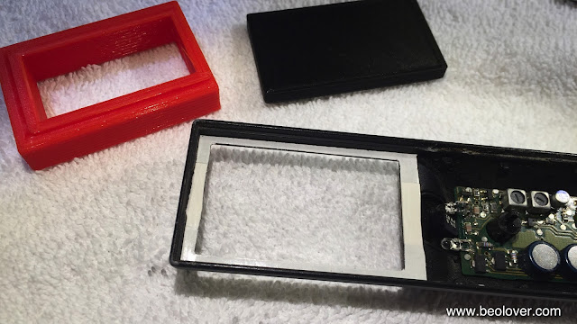
After cleaning off the glue it was time to install some industrial strength double sided tape in the frame. I had developed two more 3D printed parts that would allow me to apply the tape and then cut it to size with precision to not impair the translucency of the screen:
and with tape applied:
Then I cut the 'window' out of the tape layers using a razor blade and a matching 3D printed part that fit exactly into the display bay from the top:
This was the end result:
after removing the tape backing
Then I reconnected the display board and flipped it over with the braces in place:
After carefully pulling out the red brace part, I pressed the display into its bay, making sure that it was aligned properly:
And then came the moment of truth! Did the ribbon cable survive this stressful operation? After putting the keypad back on and inserting the three batteries it turned out that the operation was successful. The unit came alive again!
The next step is to figure out how to repair completely detached screens...another day, more Beolove!


Sunday, May 29, 2016

Beogram 4004 (5525): Leveling Platter, Final Adjustments and a Spin with Freddie Hubbard's "First Light"!

The functional restoration of the Beogram 4004 (5525) that I am restoring right now is coming to a close. After I rebuilt the DC motor, it was time to do the platter and tonearm adjustments. The platter needs to be leveled with the aluminum plates first before the arm lowering limit can be set. There are two videos on my YouTube channel that show how to adjust the platter bearing and the subchassis (in a Beogram 4000, but the process is very similar in the 4002).  This picture shows the arm lowering limit adjusted:
When lowered the needle should miss the lower parts of the strobe bars on the platter. This is an important adjustment in case the record detection mechanism fails to disable arm lowering. This is the main reason of the existence of the lowered sections. They are wisely located at the set down points to prevent damage to the needle. There is a video on my youTube channel that shows how to adjust the lowering limits.

 The next step was to adjust the tracking weight. As usual I installed a M3 nut to replace the flimsy circlip that is supposed to hold the counter weight screw in place. This upgrade makes the tracking force adjustment 'shipping survivable':
And then I calibrated the tracking force for the 1.2g point:
There is also a video about the tracking force calibration process.
The final adjustment was the tracking feedback sensitivity. I used my new 'favorite most unliked record': The soundtrack 'Gaily, Gaily' by Henry Mancini and adjusted the tracking sensor alignment:
As usual the (blue) light intensity trimmer on my SMD LED based light bulb replacement part proved useful for fine-tuning the feedback. I posted a video that shows the tracking sensor adjustment procedure in detail.

And then it was finally time for a first test drive of this Beogram! My love affair with CTI Records continues and chose one of my recent acquisitions, Freddie Hubbard's "First Light" album from 1971, which is rapidly becoming one of my favorite records. Lush arrangements by Don Sebesky complement Hubbard's precise yet sensuous trumpet play. Just awesome! What a great (and in my opinion under appreciated) direction in the evolution of Jazz! Check it out! The above discogs link has a few YouTube tracks posted.
It was interesting to listen to this record with the Axel Schürholz MMC20 cartridge (with aluminum cantilever). It sounded clean and crisp! Very awesome! This is Beolove!


Saturday, May 28, 2016

Beogram 4004 (5525): Restoration of DC Motor with Re-Infused Oilite Bearings

The final step of the restoration of the platter drive system in a DC motor Beogram (551x/552x models) is an overhaul of the motor itself. These motors came with Oilite brass sleeve bearings, which contain oil inside their porous brass material. After 30-40 years of operation this oil supply runs dry and needs to be resupplied. Dry brass bearings are the foremost cause of strong RPM drops in the DC motor Beograms. RPM increases are usually associated with oxidized RPM relay contacts or defective RPM trimmers. See here for a summary.
In the following I will show a few impressions of the process as I performed it on the Beogram 4004 (5525) that I am currently restoring. If you are interested to do this on your own, I recently made a video that demonstrates this process in detail. 

This shows the motor in place:
Three screws later the motor was on the bench:
To get at the bearings one needs to completely take it apart:
The bearings are the two small 'donuts' at the bottom of the photo. I immersed them in SAE 30 oil in a mason jar and evacuated the jar with a FoodSaver pump. Immediately the characteristic bubbles formed that indicate that the oil immersion process had begun:
After 24 hrs the process had stopped and it was time to reassemble the motor. It can be a bit of a challenge to get the bearings back in without damaging the motor. The concern with the bottom bearing are the very thin wires that connect the windings of the feedback coils. They easily break off and then some micro-solder-surgery becomes necessary to get things right again. The top bearing's challenge is to reinsert it in a way that it sits tight in its place. I designed two 3D printed fixtures to simplify this process. They allow me to apply a high but very controlled force on the tabs that hold the ring in place that presses the bearing into its spring:
After the bearing is in place I usually test it with a toothpick
It needs to move but not wiggle or be loose in any way. 'Tight fit' is the keyword here.
After the motor is reassembled it is time to test it before going further:
My benchmark is a current smaller than 30mA at an applied voltage of 5V and that the motor rotates in clockwise direction. If this is not the case, then the brush carrier plate needs to be realigned until the correct values are achieved.
After passing this test the motor can be reinserted into its noise reduction housing and implanted back into the Beogram. I usually give a restored platter drive system a 24hrs test with my BeoloverRPM device to make sure everything is o.k.. This shows the result before and after for this Beogram 4004:
The black curve is the initial test. Strong RPM spikes can be seen after a few hours of operation. They point towards issues with the RPM relay or RPM trimmers. Since there were no significant RPM drops I am speculating that the motor still would have had a few hours left on its bearings. Not surprising since the keypad looks fairly pristine on this deck and the usual finger patterns are absent, suggesting that the deck was not used much in its earlier life. But I think it is a good idea to do a full restoration of the drive system once the unit is on the bench. This will ensure trouble-free operation down the road.
The red curve was measured after the motor rebuild and exchanging relay and trimmers. The curve is very good and well within the ±0.0025% wow and flutter spec stated in the service manual.


Thursday, May 26, 2016

Beogram 4004 (5525): Replacing the RPM Indicator Light Bulbs with LEDs

No DC motor Beogram 4002 or 4004 restoration is complete without replacing the RPM indicator incandescent lightbulbs with LEDs. The purpose is not only longevity, but also DC motor stability. Since the user accessible RPM trimmers in the RPM indicator panels are actively participating in the motor control, their operating temperature is of concern. Light bulbs emit most of their energy as heat and therefore significant temperature changes occur. Replacing the light bulbs with LEDs lowers the heat load dramatically and therefore the trimmers do not change their temperature as much. This can significantly decrease RPM changes of the DC platter motor. See here for a summary of DC motor RPM issues and their cure.
So, after rebuilding the PCBs of this Beogram 4004 (5525) it was time for this procedure. Here is an impression of the original light bulbs in the RPM control panel:
The left one was exchanged at some point with a different type. The correct bulbs are difficult to find these days, one more reason to switch to LEDs. This shows my custom designed replacement boards:
These assemblies are available to other enthusiasts. This video shows how to install the LED boards. They fit precisely into the gaps in the plastic assembly that holds everything together:
The boards feature red/green LEDs tuned to emit light looking like incandescent light. I elected this design strategy to make sure that red photons are present for the illumination of the RPM indicators, which are made from red plastic. Amber LEDs such as used in some restorations of classic audio components when replacing bulbs are not suited for this task since they do not emit red light. LEDs are usually very monodisperse in their emissions, which makes them different from incandescent light that contains a wide spectrum of wavelengths.
The design of the boards permits to reinstall the bulb covers, retaining the original look even 'under the hood':


Beogram 4004 (5525): Replacing Electrolytic Capacitors and Rebuilding the DC Motor Control System

After rebuilding the arm lowering and tracking mechanisms of the Beogram 4004 (5525) that I am restoring right now, it was time to rebuild the two main PCBs. I always replace the electrolytic capacitors with modern 105C grade major Japanese manufacturer units, and I also replace the original relays and RPM trimmers with modern encapsulated units. This ensures stable functioning of the DC motor control system since it is very sensitive to contact impedance in the relay, as well as resistance fluctuations of the usually corroded RPM trimmers. Replacing these with 25 turn modern units ensures that the RPM can be adjusted precisely, and that the adjusted RPM is stable over time.

These two pictures shows the main PCB in its original condition:
The original National RPM relay and trimmers in detail:
And after restoration:
My custom designed replacement relay boards are based on modern SMD relays and a breakout that has the exact pinout of the original relay:
These drop-in ready replacement relays are available to other B&O enthusiasts, just send me an email or use the contact form on my blog. This shows the relay and the trimmers installed:

I always orient the trimmers that their adjustment screws are flush with the through-holes in the PCB, and that RPM increase corresponds to clockwise turning:
After completing the main PCB I turned my attention to the output (#8) PCB. This shows it in original condition:
The main difference to 4002 output boards is the remote control section to the right of the black mounting standoff. The 4004 can be controlled via the Beomaster 2000 using an early form of beolink. Essentially start, stop and arm lift can be controlled.

This shows the output relay in detail:
And after replacement of capacitors and relay:
As usual, I also installed a grounding switch next to the output cable jack. This switch allows the connection of system and signal grounds in case grounding issues cause humming. An example is the use of a DIN5-to-RCA adapter without system ground breakout.

The last step was to replace the original power supply reservoir capacitor. I developed a 3D printed adapter for a modern, smaller unit that fits exactly into the capacitor bay in the enclosure:
Pretty, isn't it?? This is Beolove! On to the DC motor restoration with oil infused oilite bearings...


Wednesday, May 25, 2016

Beogram 4004 (5525): Restoration of Arm Lowering and Tracking Mechanisms

As usual I started the restoration of this Beogram 4004 (5525) with the arm lowering mechanism and the tracking system. Here is a picture of the solenoid and the damper that control the arm lowering:
I removed the linkages and the damper for cleaning and lubrication:
This video shows how to rebuild the tone arm mechanism in detail. After putting everything back together I turned my attention to the linkage that connects the damper to the arm. For getting to this one has to take out the sensor arm> This shows the sensor arm from the back:
and after removal:
Then I removed the circlip and the spring that hold the linkage down and removed it:
This video shows how to get to the damper to arm linkage and re-lubricate it. After putting everything back together it was time to adjust the lateral parallelism of the arms:
Then I replaced the original tracking sensor light source with one of my SMD LED based replacements to ensure trouble free operation down the road. This shows the original fixture:
After taking off the light source assembly the tracking control aperture becomes visible:
Then I installed the replacement:
It has a potentiometer which allows easy fine tuning of the tracking feedback via changing the light intensity of the LED in the assembly. This part is available. Just send me an email or use the contact form on the side bar of the blog. There is a video that shows the tracking sensor adjustment procedure in detail. 

The next step was to exchange the wobbly original plastic pulley with a new aluminum pulley provided by Nick (I'll be happy to get you in touch with him if you need one!). This shows the original pulley:
And the new one:
Allright! All good again in the arm lowering and tracking departments!