Featured Post

Beolover SyncDrive: DC Platter Motor Replacement for Beogram 4002 and 4004 (Type 551x and 552x)

Late Beogram 4002 and the 4004 (Types 551x and 552x), which have DC platter motors instead of the earlier synchronous AC motors usually suff...

Monday, March 14, 2016

Beogram 4002 (5513): Repair of Bent System Ground Terminal

After installing my new BeoloverRIAA pre-amplifier design in the Beogram 4002 that I just finished up, I set out to put the enclosure back together and bolt on the hood when I realized that I had completely forgotten about the bent and damaged system ground terminal in the back:
It turned out that I needed to cut the bold off with a saw since the threads were too damaged to get the  rusty nut off that was installed. After getting the bolt out I installed a new 3 mm bolt with the appropriate insulating shoulder washers:
O.k...it seems I am done now! Beolove is in details! Time to ship this 4002 back to its owner!

Saturday, March 12, 2016

BeoloverRIAA Preamp: First Installation of Finalized Design in Beogram 4002

I received the redesigned PCBs for my Beogram 4002 internal RIAA pre-amplifier a couple days ago. The fact that this pre-amplifier runs from the single rail Beogram-internal power supply posed some interesting design challenges that made it necessary to go through a couple of design interactions to achieve a satisfying signal-to-noise ratio. See my previous post for more details on the design process.

But now I think this design is ready for primetime. I populated one of the boards and implanted it into  a first Beogram 4002. Here are a few impressions. This shows the redesigned board with its 3D printed mounting support:
The board grew a bit in size to accommodate my improved power supply design.
This shows the mounting support on the pins of the board:
The pins fit directly into the solder points of the original output relay of the Beogram 4002. In fact, the RIAA preamp board maintains the full functionality of the non-amplified standard output of the Beogram. That is the reason that there are two relays on the board. One for the amplified output and one performing the function of the original output relay
This means the user can easily switch the deck between RIAA and standard output by simply plugging the connectors either into the amplifier board or into the original connectors on the output board (see below).
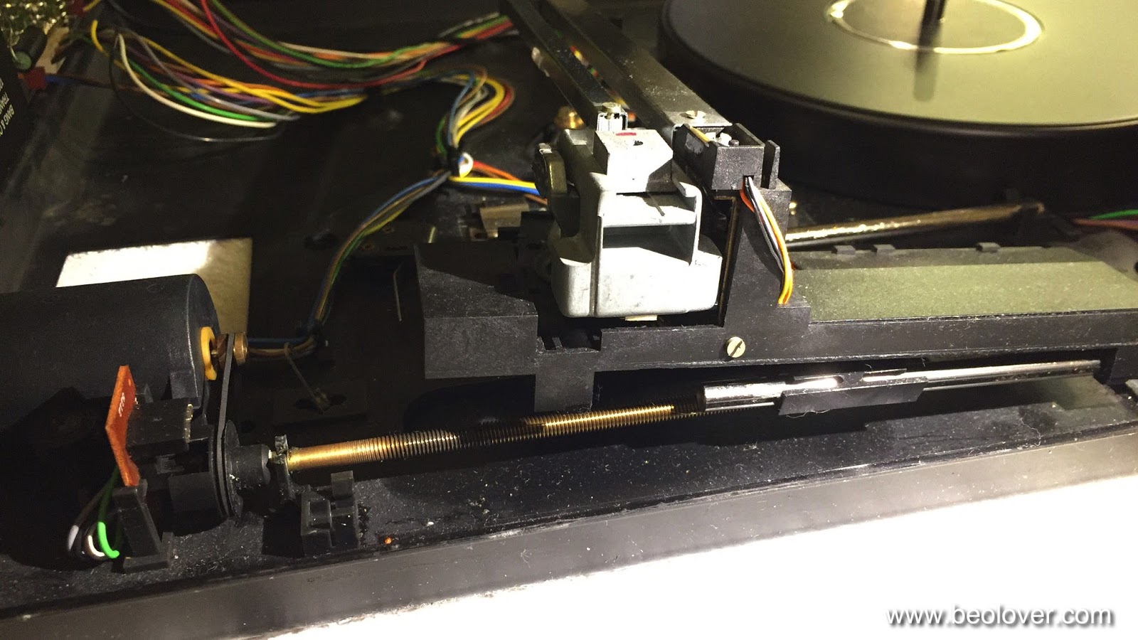
This shows the board installed on PCB 8. I had to move the grounding switch that I had initially installed to a different location underneath the original input connector:
This shows PCB 8 installed back in the Beogram 4002:
The input and output connectors are shown inserted into the amplifier board, i.e. this is the configuration for amplified output. The original non-amplified output can be configured by inserting the connectors into the original board-to-wire connectors on PCB 8:
Here an impression from the front of the deck:
After reassembling the Beogram I connected the output cable to my QA400 audio analyzer and measured signal-to-noise curves:
Nothing changed from the prototype as expected. The red curve shows the noise floor with the Beogram started and the arm down next to the platter (i.e. not touching the record). The noise floor at 1kHz is still about -100dB.  That gives the baseline for all further noise considerations. The large noise dB numbers stated for many available RIAA preamps are measured with the inputs shortened to ground, which is pretty much meaningless since the main noise source other than from the vinyl itself is the cartridge. Due to its own impedance (and the necessary 47k input resistance on the amp) the generated Johnson noise vastly exceeds the input noise of modern low-noise opamps such as the LM833 used here. 
The blue curve illustrates that the noise generated by the vinyl surface is yet another factor 3 or more higher. It was measured while playing the 'rumble track' on my Analogue Test LP. I used a good condition MMC20EN for these measurements. It is obvious that the RIAA amp performance is such that the noise while playing a record is not increased significantly. 

This beolovely performance inspired me to celebrate my latest addition to the 'Beolover parts catalog' with one of my favorite 45s of my youth (don't judge me by this!...;-), 'Dance Hall Days' by Wang Chung:
Allright, looks like this Beogram is ready to be shipped back to its owner!


Friday, March 11, 2016

BeoloverRPM: RPM Measurements on a Beogram 8002 and Comparison to a DC Motor Beogram 4002 (5513)

My recently developed BeoloverRPM device determines the measured RPM via the time it takes between the 'ribs' on the platter to cross the sensor field of vision. It is simple math to determine the RPM from that, and I was pretty confident that my measured absolute RPM numbers were accurate. However, there is always the possibility of human error, and so I was itching to test the BeoloverRPM on a microprocessor controlled Beogram 8002, which should have a very good RPM accuracy and stability.
So the Beogram 8002 that I just resurrected was in the 'right place at the right time' for this! I used my most recent version of the BeoloverRPM that can be set up on top of the aluminum plates, i.e. the Beogram does not need to be put into service position for a RPM measurement. I did two measurements, for 33.33 RPM
and for 45 RPM:
And it appears the Beogram 8002 and the BeoloverRPM microcontrollers are in happy agreement! The Beogram is spot on, and the BeoloverRPM appears to deliver a precise RPM measurement.

I measured a RPM performance curve for a few minutes while having my 7" test single (Donald Byrd: Black Byrd) on it. This graph shows the curve in comparison with a DC motor Beogram 4002 (5513) in perfect condition:
The red curve on top was measured on the Beogram 8002, while the blue curve below represents the performance of the 4002. We see that both units have a periodicity in their RPM, but the 8002 has a noticeably smaller variation than the 4002. The periodicity itself is unavoidable in a feedback-based control system since a PID mechanism needs some change to be able to operate. The art of designing such systems is to get the change as small as possible, while still being able to run the mechanism in a stable way.
But we clearly see here that a microcontroller based feedback system is superior to an analog system that depends on temperature, component tolerances and probably the moon phase (that was a joke...;-). In practical terms this difference is probably not perceivable by a human ear, but the 8002 definitely represents progress. I am curious to see how the AC motor Beograms perform in comparison...stay tuned for the next episode of this exciting unfolding story...;-)


Thursday, March 10, 2016

Beogram 8002: Adjusting the Tracking Sensor Aperture

During my test drive of the Beogram 8002 that I just brought back to life I was pondering Grover Washington, Jr's artistic output while listening to 'Knucklehead' on his seminal 'Mister Magic' record, when I realized that the tonearm was not tracking properly. It ran at a much to large angle relative to the sensor arm. So it was time to put on my least liked record, some free jazz by Sam Rivers, and do the tracking sensor adjustment procedure! This shows the arm with the original misadjusted sensor. It is not parallel with the sensor arm:


Luckily one can adjust the tracking sensor aperture without putting the 8002 into service position. All that is necessary is to remove the black panel that is under the arms in their home position and then the screw that controls the aperture can be accessed:
It is a good idea to drive the carriage a bit towards the center of the record. That allows to fit a small screwdriver into the enclosure for better fit into the screw head:
The service manual prescribes to block the platter with your hand to do the adjustment (one needs to achieve a setting of the aperture that the carriage starts moving after 2±1 turns of the platter after the needle touches down). This seemed a bit brutal to me, and I settled for simply letting the platter spin and then pressing 'play' to engage the needle. Then I counted the rotations while watching the spindle that drives the carriage. A few small adjustment steps forth an back and I was able to achieve the 2±1 spec. Here is an impression of the arm when the aperture is properly adjusted:
The arm is now virtually parallel with the sensor arm while the record is playing. This is Beolove! Now away with Sam Rivers and back to Grover Washington, Jr.! A much smoother sound!!..;-).


Beogram 4000: Adjusting the Platter, Floating Chassis, Arm Lowering Limits and Tracking Weight

Now it was time to adjust the platter, the sub-chassis and the arm lowering limits and tracking weight.   Check my Beogram 4000 page for some posts and videos about this procedure. But first I needed to replace the cabinet guiding washers that were either replaced with simple washers or had cracks:

There is a video about this procedure in my Beogram 4002 playlist. The guidance washers can be ordered directly from my Shapeways store. This is the direct link to the part.

These washers are very important for proper seating of the aluminum plates, which in turn is essential for being able to properly adjust the sub-chassis and platter height. This shows one of the washers installed:
They are a faithful reproduction of the excenter washers used in later models.

Then I adjusted the platter and the chassis to achieve a concentric location of the platter in the cutout of the main aluminum plate:
After the chassis and the platter are adjusted the arm lowering limit can be set. There is a video on my youTube channel that shows how to adjust the lowering limits. This is a very important procedure since the control system of the 400x cannot guard against photosensor failure in the sensor arm. If the sensor fails the arm will be lowered whether there is a record or not, possibly endangering a very expensive cartridge. The correct adjustment of the arm lowering limit can prevent stylus failure if that happens.

After this the tracking force can be calibrated. There is also a video about the tracking force calibration process.

And then it was time to give this Beogram 4000 a test drive! Oh, wait...not yet! It occurred to me that I hadn't adjusted the Wien oscillator that drives the AC motor. It needs to oscillate at a certain amplitude. This is done by connecting the oscilloscope between the coupling and phase capacitors of the motor and ground. After adjusting the 33 RPM voltage I got these nice curves. This one is for 33 RPM where 6.5V RMS need to be adjusted.
And the depending (there is nothing to adjust) curve for 45 RPM:
O.k....now it was finally time to do some listening! I selected a recent addition to my vinyl collection, a compilation of Marc Moulin's best tracks of his Placebo band between 1971 and 1974. In my opinion his most creative time. This is some awesome stuff! It sounds like it was generated last year by some hipsters in NYC...way ahead of its time!
Another interesting aspect of this issue is the almost fully transparent vinyl, which makes this a great test record for the disc detection mechanism of the Beogram!

Wednesday, March 9, 2016

Beogram 8002: Adjustments and Some Final Touches

I recently repaired a Beogram 8002 that showed some strange behavior. Before I send it back to Australia, it was a good moment to clean up a few other small issues. I first focused on the tonearm. Its horizontal parallelism was a bit out of whack (the arm was a mm higher than the sensor arm):
This is an easy adjustment but one has to lift the carriage up. This is easiest done by pulling out the back slide rod (it just pops out of its plastic brackets by using a screwdriver for forcing it up). Then the carriage can be lifted:
This is how it looks from below:
The adjustment screw is right below of my thumb. For lowering the arm it simply needs to be turned a bit CW. I did a 1/3 rotation and that fixed the issue:
Then I closed the deck from the service position and did the tracking force adjustment. For that it is best to drive the arm a bit in onto the aluminum plate without the platter installed that the arm can be lowered onto the tracking weight gauge:
It turned out that the weight adjustment scale was adjusted perfectly, i.e. I did not have to do anything. The next step was to install new rubber bumpers into the hood to improve the 'hood closing sound' (yes, this is important!..;-). I extracted the bumper remnants from the orifices that hold the bumpers with a 2 mm drill bit that I outfitted with a 3D printed handle for enhanced control and convenience:
Then I glued in snippets of a 1/8" thick O-ring and razor bladed them off using my 3D printed cutting template that has the right thickness to keep the hood level with the bumpers in place:
With the new bumpers installed I also adjusted the hood damper to give it a smoother closing feel.

After that I cleaned the aluminum surfaces with Mr. Clean Magic Eraser Pads. This shows the surface before:
And after:
Much shinier, I'd say!

The final touch was to adjust the platter height to be 2 mm all around its circumference. This shows the adjustment of the spring on the right side:
And then it was time to give it a spin!
I chose 'Mister Magic', one of Grover Washington, Jr's 'KUDU' label records (KU 20). I just love the smooth arrangements on this record. And what a great cover! It is a shame (or great opportunity...;-) that one can buy this lovely vinyl for about $5 on Discogs in NM condition! In my opinion a greatly under-appreciated work by an extremely talented artist! My favorite track is 'Passion Flower', which is an amazing and mysterious journey through a lush soundscape. Perfect to enjoy a lovely Beogram 8002!


Beogram 4000: A New DIN 5 Cable and a Grounding Switch

The Beogram 4000 that I am currently restoring had a cutoff output cable:
This is already the third 4000 that I am working on that had a mutilated cable. I really wonder why some people are attracted to cutting off cables...very strange! Anyway this gave me an opportunity to install a modern cable with double braided and foil shielding, which is the best way to keep interference from our precious MMC signals on their way to the amplifier.
I installed a quality Neutrik gold plated all-metal DIN5 plug on the business end of the cable:
I always like the looks of these plugs!

Here is the other end inside the turntable. First I prepared the cable for installation:
and then I soldered it in at the terminal block. This shows the original setup with my standard grounding switch already installed. This switch allows to connect signal and system grounds in case a RCA adapter without grounding breakout is used:
This shows the set-up with the new cable:
All good again in the 'signal path department'! Platter alignment and floating chassis adjustment are next!