Featured Post

Beolover SyncDrive: DC Platter Motor Replacement for Beogram 4002 and 4004 (Type 551x and 552x)

Late Beogram 4002 and the 4004 (Types 551x and 552x), which have DC platter motors instead of the earlier synchronous AC motors usually suff...

Tuesday, April 27, 2021

Beogram 4002 DC Motor Restoration: A New Tool on the Bench and the Importance of the Orientation of the Top Bearing

I recently received another DC platter motor from a Beogram 4002 for restoration. This shows the motor as received:
After removing the outer housing it was immediately clear that this motor had already received some 'attention'. The scratches and marks on top and on the tabs of the bearing assembly indicated that the top bearing had been removed once already:

This posed an issue since I know from painful past experience that if one bends these tabs twice they can easily break off, and this usually relegates the motor to the spare parts bin. After I opened the motor up I also found mangled brushes. Luckily the feedback pickup coils were not damaged.

So I proceeded and extracted the bottom bearing and submerged it in oil and pulled a vacuum. Immediately bubbling started indicating that the bearings most likely had not been oil infused during the previous repair attempt.

So I added the entire top part of the motor housing into the oil in the hope that the top bearing would also infuse while still installed. A lot of bubbles came out indicating that there are some nooks and crannies behind the magnets etc...:

After about 3 days no more bubbling could be seen and I removed the parts from the oil:

\
I waited a day to let as much oil as possible drain from the motor housing. Then I ultrasonically cleaned the housing a few times in water with detergent, followed by a course in isopropyl alcohol to remove the excess oil from the housing. These motors cannot run well if there is oil 'sloshing' around on the inside. The only good place for oil is inside the porous bearing material from which it can slowly leach out onto the shaft as it rotates.
The next step was to straighten out and clean the brushes:
After this I re-assembled the motor for the first time and tried to run it. No cigar, though. All that happened was that my bench supply went straight into current limiting mode indicating a short circuit. This is usually indicative of one or more shortened spark snubbers on the rotor coils.

I opened the motor up again. This shows the rotor with the original spark snubbers. They are the three wired 'blobs' on top of the windings (one is invisible behind the commutator, one has a faint red dot on it)
These can be replaced with modern bi-polar surface mount TVS devices:


One can bend their contact tabs out a bit, and then they fit neatly between the rotor poles:
If you try this at home, note that the TVS packages need to be below the commutator assembly. Otherwise they can interfere with the brushes when the motor rotates (an ugly noise!). After this surgery, I put the motor back together and installed it in one of my Beogram 4002s for an RPM stability test with my BeoloverRPM device:
It allows logging the RPM in 10s intervals for long periods of time. The blue curve in the graph below is the curve that I measured. While basically stable, there were ugly spikes indicating some occasional spontaneous RPM increases. Not very beolovely!

And this is when invention happened! I knew from past experience that maintaining the original rotational orientation of the top bearing can help reducing the number of problematic RPM stability measurements. This is why I started marking the orientation of the top bearing relative to the housing with a sharp needle that I can install in the exact same orientation after the oil infusion. This practice essentially eliminated issues with RPM stability after the restoration process. 
My hypothesis about the necessity to keep the bearing orientation is that these bearings wear unevenly over time due to the pull of the platter belt. This lateral torque on the shaft probably results in the formation of a 'more polished' area towards the direction of the platter center.
I think, one can actually sometimes weakly observe this polished area in some bearings when shining light through them.
If the bearing is oriented differently after the re-assembly a more rough area is faced by the shaft in the direction of the belt-pull, and this seems to cause some weak inconsistent friction changes that can occasionally throw off the motor control circuit, inducing an overcompensation that causes the observed spikes. In my experience these spikes are always to higher RPM. I also observed in the past that these spikes get slowly weaker after running the motor for many days, supporting the theory of the worn-in region on the bearing. I am actually wondering if these Beograms had a similar burn-in period when they were used for the first time when new. The spikes are probably too weak to be audible, and 1970s RPM measurements involved using a test record with a frequency analyzer, i.e. the measurement integrated over time to some extent and may have missed such fast variations. Theories...;-)

Anyway, the issue at hand was that the original orientation of the top bearing of this motor was unknown due to the previous repair attempt. And I did not want to run it for 2 weeks in the hope to get rid of the spikes.
So I settled for the design of a 'burn-in tool', which would enable an accelerated wear-in process. This is what I came up with:
I had a 1 inch ball bearing laying around and so I designed this jig with a 3D printed pulley that fit on top of the bearing and a holder for the motor in an appropriate distance to allow for a decent pull exerted by the rubber band, which came from a bunch of organic green onions that my wife prefers to buy. I estimate the pull is a few times stronger than the platter belt, and the rotation (at 4V) is maybe another 3x compared to 33RPM in-situ. This estimate comes from the fact that the platter RPM is usually about 90-100 rpm if the pickup coils of the motor are damaged, which eliminates the RPM control and the motor runs as fast as it can.

I ran the motor in this setup for about 4 days, and then I installed it back in the Beogram and measured another 24 hrs RPM stability curve. And what I measured is the red curve in the graph above. 
So it seems this approach may work if the bearing orientation is unknown prior to restoration. This motor is ready for duty again!


Monday, April 26, 2021

Beogram 4004 (5526): A First Look

A while ago I received a Beogram 4004 (5526) from Pennsylvania for restoration. This unit arrived in the original box but double boxed:

I am not a fan of using the original boxes. The styrofoam is pretty hard, and I am worrying about the old brittle PCBs a bit etc...but this unit seems to have braced transport fairly well:
Under the hood I found this note pointing at a MMC 20CL cartridge that sat unprotected on the arm. A recipe for disaster! Especially with the arm unsupported.
Oh well, I had a look at the cantilever, and the tip was still on it. So there is a chance that it may actually have survived. But we will hear when I play the deck for the first time after the restoration. Anyway, I secured the precious thing in a Beolover MMC box:
The cosmetic condition of the unit is pretty decent. There are no significant damages in the aluminum surfaces.
Sadly there is a deep reaching strange 'spot' on the plexiglass cover, which seems unpolishable. It is very deep. I wonder what happened! But this means there may be a new cover from a donor in the future for this 4004. Too bad since the cover is otherwise in very good condition. Another one bit the dust.
The keypad has the typical damage on the START key where the clear coat has worn off:
Under the hood the condition seems pretty original. I was not able to see any obvious traces of previous 'human interaction' at this point:
After this inspection I plugged it in and pressed start. A screeching noise indicated a running DC platter motor with dry bearings. Nothing special at this age. The carriage started moving sluggishly towards the LP setdown point and upon reaching it the solenoid engaged. Good signs of life!
In summary, this seems to be a straight forward restoration project.


Beogram 4002 DC Motor Restoration

I recently received a Beogram 4002 DC platter motor from Norway for some TLC. This shows the motor as received:

I took it apart to extract the bearings for oil infusion:
The bearings are the two small donuts on the black pad up front. I immersed them in motor oil and pulled a vacuum. Immediately, bubbling started as the air was drawn from the porous bearing material to make room for fresh oil:
After about three days the bubbling stopped and I extracted the bearings:
Then I reassembled the motor and installed it in one of my Beogram 4002s for a 24 hrs RPM stability test with the BeoloverRPM device:
It logs the RPM in 10s intervals for extended periods of time. This is the curve I measured for this motor.
This is as good as it gets with the Beogram 4002 DC platter motors! This motor is back in business and will be sent back to Norway soon!


Beogram 4004 From Canada: Begin The Listening Tests

This Beogram 4004 turntable is doing what it was built to do...play records beautifully.

I finished record play testing of the Beogram earlier on the workbench.


Satisfied with the performance on the workbench I reinstalled the deck panels.


Installing the deck panels can be quick and easy or it can take a while and require a lot of adjusting.
This Beogram was somewhere in between.  The panels fit onto the frame in a specific way but on each of the three floating suspension leaf springs there is a mounting post for the panel that sits on top.
If the deck panels do not appear to be properly aligned the posts may need to be bent appropriately to align the panels.

Similarly, the screws that the leaf springs fit over and are adjusted with may need to be bent in order to shift the floating suspension so the platter is centered in the hole of the deck panel.
Note: Be careful with bending the posts and screws. Make sure the threads of the screws are not damaged if you have to adjust them. I use rubber sleeves made for my pliers that prevent any metal to metal contact.

Here is a photo of one of the three leaf spring mounts. It shows the deck plate post and the leaf spring adjustment screw.


Always assemble everything without making any adjustments first.  If your Beogram 400x turntable is all original and hasn't been readjusted then everything should fit properly without any adjustments except possibly for tension on the leaf springs to adjust the platter height (relative to the deck).

If things do not fit properly then likely someone in the past tried (unsuccessfully) to make adjustments or someone swapped out the deck panels at some point.

Here is the Beogram 4004 moved to my office where I will be doing some listening tests for the next week or two while I set up and polish the dust cover.

I was in the mood to hear some Fairport Convention.  I recently picked up a 180 gram re-issue of "What We Did On Our Holidays" as well as a 1976 copy of  their 1969 release "Unhalfbricking".
I attached an MMC-20CL cartridge for these listening tests and the Beogram 4004 plays perfectly.


Saturday, April 24, 2021

Beogram 4004 From Canada: Speed Indicator Lamps, Circuit Measurements and First Record Play

 This Beogram 4004 is getting closer to completion.  I have reached the point where the Beogram can detect and play a record.

To get to this point I had to finish up one more bit of electrical restoration work. That was the replacement of the incandescent speed indicator lamps with Beolover LED replacement lamp assemblies.
It has been noted before on the Beolover Blog posts but bears mentioning again...the speed indicator lamps are part of the Beogram 4002 platter motor control circuit and cannot just be replaced with an LED and a current limiting resistor.  The Beolover speed indicator lamp assembly uses an LED (more than one actually) but it is also a circuit designed to behave as the incandescent lamp does in the control circuit.
There is an added benefit to upgrading to this Beolover lamp assembly.
Platter speed stability testing on the Beogram 400x has shown that the LED assemblies run cooler and are more stable than the original incandescent lamps. This adds a little more stability to the platter motor speed. That stability improvement goes hand in hand with the upgraded speed selection relay, speed adjustment trimmers and of course the restoration of the platter motor.

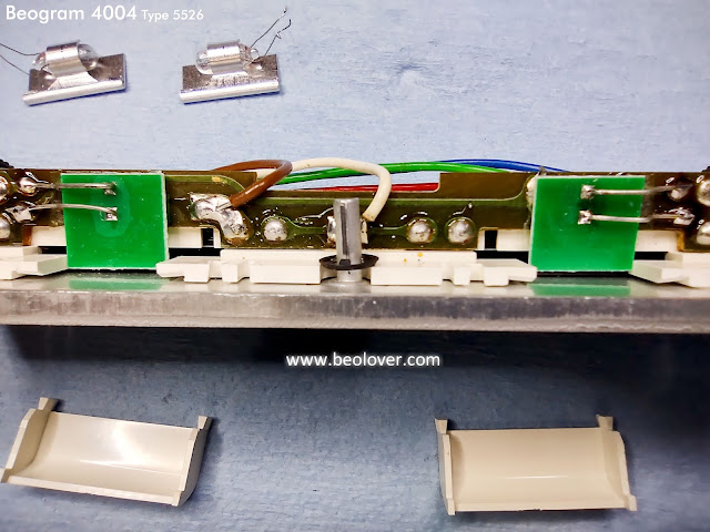
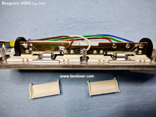
Here are photos of the speed indicator lamp replacement.


Before jumping right to playing a record I had to check the arm lowering limit, the parallelism of the tonearm, set the tangential arm tracking sensor, adjust the platter motor speeds and check the important Beogram circuit signals with an oscilloscope.

Here is the arm lowering limit result.


Here is the arm length and parallelism check


The tracking sensor adjustment can take a few iterations of adjusting the sensor diaphragm position and checking the servo motor control circuit tracking sensitivity.
There is a detailed discussion of the procedure here.

My result was this Beogram 4004 being able to detect and play a record.


Very nice...but is the Beogram circuitry performing correctly?

I connected up some wires to look at various signals on an oscilloscope.


Here is what the oscilloscope measures at the 1TR3-Collector when the Beogram fixed arm sensor sees and empty platter.


The record detection circuit signal looks just like it should.

Now here are photos of various Beogram record play functions and what the MR/MB servo motor signals are doing as well as the run-off stop (position sensor) signal and arm lowering solenoid signal.

This first photo shows the solenoid signal when it receives the command to lower the tonearm.
The signal starts off at around 30 VDC to engage the solenoid.
After around 30 milliseconds the solenoid engage signal drops in voltage until about 1.5 VDC which it remains at until the arm is commanded to raise.  The 1.5 VDC is able to hold the solenoid in the arm lowered position while a record is playing.


This photo of the same event is at a longer time scale to show both the solenoid engage event as well as the servo motor accelerating through the lead-in groove.


Notice that the position sensor has a pulse where the 30cm set down bar was detected.
You can also see the Servo Motor MR signal accelerate on the run-in groove after the stylus set down on the record.

I looked at these same signals when the Beogram was playing a record and the Fast Forward ("<<") button was pressed to scan forward.


Prior to the Fast Forward button press the Servo Motor MR signal shows it driving the servo motor to track the record with the stylus navigating the record groove.
When the Fast Forward button is pressed the Servo Motor MR jumps up to its high speed and the voltage on the arm lowering solenoid is released (causing the arm to raise).

The signals are similar when the slow forward scan button is pressed.


The last event I wanted to observe on the oscilloscope was the run-off stop event. That is when the stylus catches the record run-out groove.
The Beogram 4004 run-off stop circuit detects that event and causes the Beogram to raise the tonearm and return to home. This happens before the end stop (ES) switch is reached.  For the case where there is no record on the platter and the Beogram fixed arm sensor is scanning forward to look for a record, the ES switch will catch the end of where a record would be and returns the Beogram to home.


You can see that the Servo Motor MR signal increases speed to keep up with the stylus accelerating with the record run-out groove.  The black markings on the position scale pass through the position sensor and the resulting run-off stop signal causes the circuit to generate a stop/return command.
The Beogram raises the tonearm and the Servo Motor MR signal drives the tonearm assembly home.

Instead of playing a test record for the purpose of making measurements I think it is time to reassemble the Beogram 4004 cabinet and test play some records for a listening test.