This Beogram 4004 is getting closer to completion. I have reached the point where the Beogram can detect and play a record.
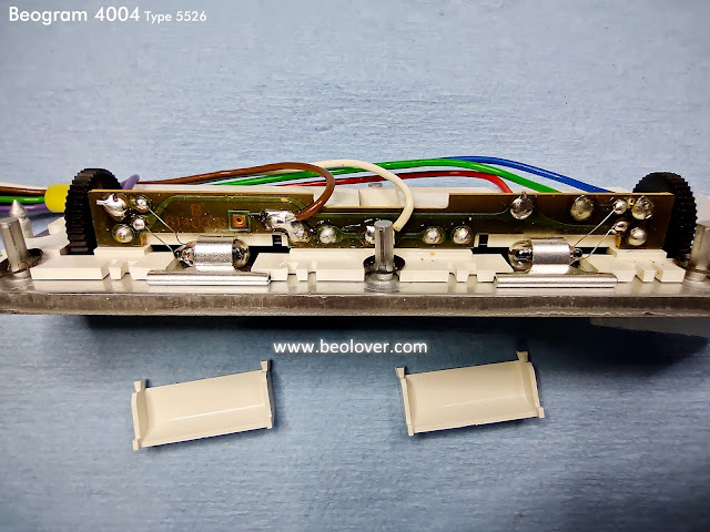
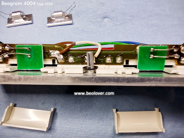
To get to this point I had to finish up one more bit of electrical restoration work. That was the replacement of the incandescent speed indicator lamps with Beolover LED replacement lamp assemblies.
It has been noted before on the Beolover Blog posts but bears mentioning again...the speed indicator lamps are part of the Beogram 4002 platter motor control circuit and cannot just be replaced with an LED and a current limiting resistor. The Beolover speed indicator lamp assembly uses an LED (more than one actually) but it is also a circuit designed to behave as the incandescent lamp does in the control circuit.
There is an added benefit to upgrading to this Beolover lamp assembly.
Platter speed stability testing on the Beogram 400x has shown that the LED assemblies run cooler and are more stable than the original incandescent lamps. This adds a little more stability to the platter motor speed. That stability improvement goes hand in hand with the upgraded speed selection relay, speed adjustment trimmers and of course the restoration of the platter motor.
Here are photos of the speed indicator lamp replacement.
Before jumping right to playing a record I had to check the arm lowering limit, the parallelism of the tonearm, set the tangential arm tracking sensor, adjust the platter motor speeds and check the important Beogram circuit signals with an oscilloscope.
Here is the arm lowering limit result.
Here is the arm length and parallelism check
The tracking sensor adjustment can take a few iterations of adjusting the sensor diaphragm position and checking the servo motor control circuit tracking sensitivity.
There is a detailed discussion of the procedure here.
My result was this Beogram 4004 being able to detect and play a record.
Here is what the oscilloscope measures at the 1TR3-Collector when the Beogram fixed arm sensor sees and empty platter.
The record detection circuit signal looks just like it should.
Now here are photos of various Beogram record play functions and what the MR/MB servo motor signals are doing as well as the run-off stop (position sensor) signal and arm lowering solenoid signal.
This first photo shows the solenoid signal when it receives the command to lower the tonearm.
The signal starts off at around 30 VDC to engage the solenoid.
After around 30 milliseconds the solenoid engage signal drops in voltage until about 1.5 VDC which it remains at until the arm is commanded to raise. The 1.5 VDC is able to hold the solenoid in the arm lowered position while a record is playing.
This photo of the same event is at a longer time scale to show both the solenoid engage event as well as the servo motor accelerating through the lead-in groove.
Notice that the position sensor has a pulse where the 30cm set down bar was detected.
You can also see the Servo Motor MR signal accelerate on the run-in groove after the stylus set down on the record.
I looked at these same signals when the Beogram was playing a record and the Fast Forward ("<<") button was pressed to scan forward.
Prior to the Fast Forward button press the Servo Motor MR signal shows it driving the servo motor to track the record with the stylus navigating the record groove.
When the Fast Forward button is pressed the Servo Motor MR jumps up to its high speed and the voltage on the arm lowering solenoid is released (causing the arm to raise).
The signals are similar when the slow forward scan button is pressed.
The last event I wanted to observe on the oscilloscope was the run-off stop event. That is when the stylus catches the record run-out groove.
The Beogram 4004 run-off stop circuit detects that event and causes the Beogram to raise the tonearm and return to home. This happens before the end stop (ES) switch is reached. For the case where there is no record on the platter and the Beogram fixed arm sensor is scanning forward to look for a record, the ES switch will catch the end of where a record would be and returns the Beogram to home.
You can see that the Servo Motor MR signal increases speed to keep up with the stylus accelerating with the record run-out groove. The black markings on the position scale pass through the position sensor and the resulting run-off stop signal causes the circuit to generate a stop/return command.
The Beogram raises the tonearm and the Servo Motor MR signal drives the tonearm assembly home.
Instead of playing a test record for the purpose of making measurements I think it is time to reassemble the Beogram 4004 cabinet and test play some records for a listening test.


No comments:
Post a Comment
Comments and suggestions are welcome!