The final incandescent bulb to be replaced in the Beogram 4002 (5523) that I am restoring right now was the bulb in the sensor arm. This shows the sensor compartment pulled out from the arm with the original light bulb still in place:
I extracted the bulb. This shows the bulb next to the flex PCB based LED assembly:
The flex PCB folds up that the LED board fits into the compartment:
This shows the LED in action after installation:
It is a warm white light LED, which ensures that it has enough red photons to back-illuminate the red B&O logo at the front of the arm.
Whenever a change is made to the record detection system of the 4002 the sensor response needs to be measured and qualified. This is done by measuring the sensor signal at the collector of TR3, which amplifies the AC signal produced by the photo cell in the arm when the black ribs move underneath the arm. This shows the sensor signal after installation of the LED:
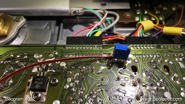
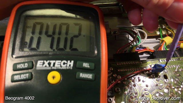
The waveform needs to dip to zero and raise up to ~6V. In this case the signal dipped well enough (if this is not the case, adjust the LED or bulb forward/backward in the compartment until the signal comes close to zero), but it did not quite reach 6V, topping out at about 5V. This is usually the result of an improperly biased TR3. Since the base of TR3 is only biased via a 1 MOhm resistor to the collector, the operating point of TR3 depends on its current gain value H(fe). H(fe) can considerably vary between transistors with of the same type due to manufacturing fluctuations. Therefore not all Beograms show the prescribed 4V DC voltage at the collector of TR3. Indeed, this Beogram measured only 3.3V, which explains the too low sensor signal. This can be cured by the installation of a 2MOhm trimmer instead of the fixed value 1MOhm resistor commonly found installed as R26. This shows the trimmer installed on the solder side of the board allowing adjustment with the board installed:
With a multimeter connected at the collector, the voltage can now be adjusted to 4V:
After this adjustment the waveform showed the prescribed 6V amplitude. This record detection circuit is now working properly.


No comments:
Post a Comment
Comments and suggestions are welcome!