Featured Post

Beolover SyncDrive: DC Platter Motor Replacement for Beogram 4002 and 4004 (Type 551x and 552x)

Late Beogram 4002 and the 4004 (Types 551x and 552x), which have DC platter motors instead of the earlier synchronous AC motors usually suff...

Sunday, June 19, 2022

Beogram 4004 Type 5526: Starting in on the restoration work - Part 1

Since the last post I have jumped into the Beogram 4004 restoration tasks.
I am going to show the before and after pictures of the PCB 1 and PCB 8 capacitor replacements but I am also going to show a few other tasks that I performed along the way.

Before tackling the PCB 1 and PCB 8 part replacements I wanted to get the problem of the End Switch (ES) and Switch On/Off (SO) switches resolved.

The previous post showed the broken ES switch.  I decided to replace both the ES and SO switches with a good set from a spare Beogram 4002 Type 5513 unit.

Here are a couple of before photos -


Here are the two replacement switches installed -


While I had the Beogram 4004 floating chassis components in front of me I continued by disassembling components I am going to replace or restore.

Next, I removed the servo motor and the tangential drive spindle/pulley assembly.
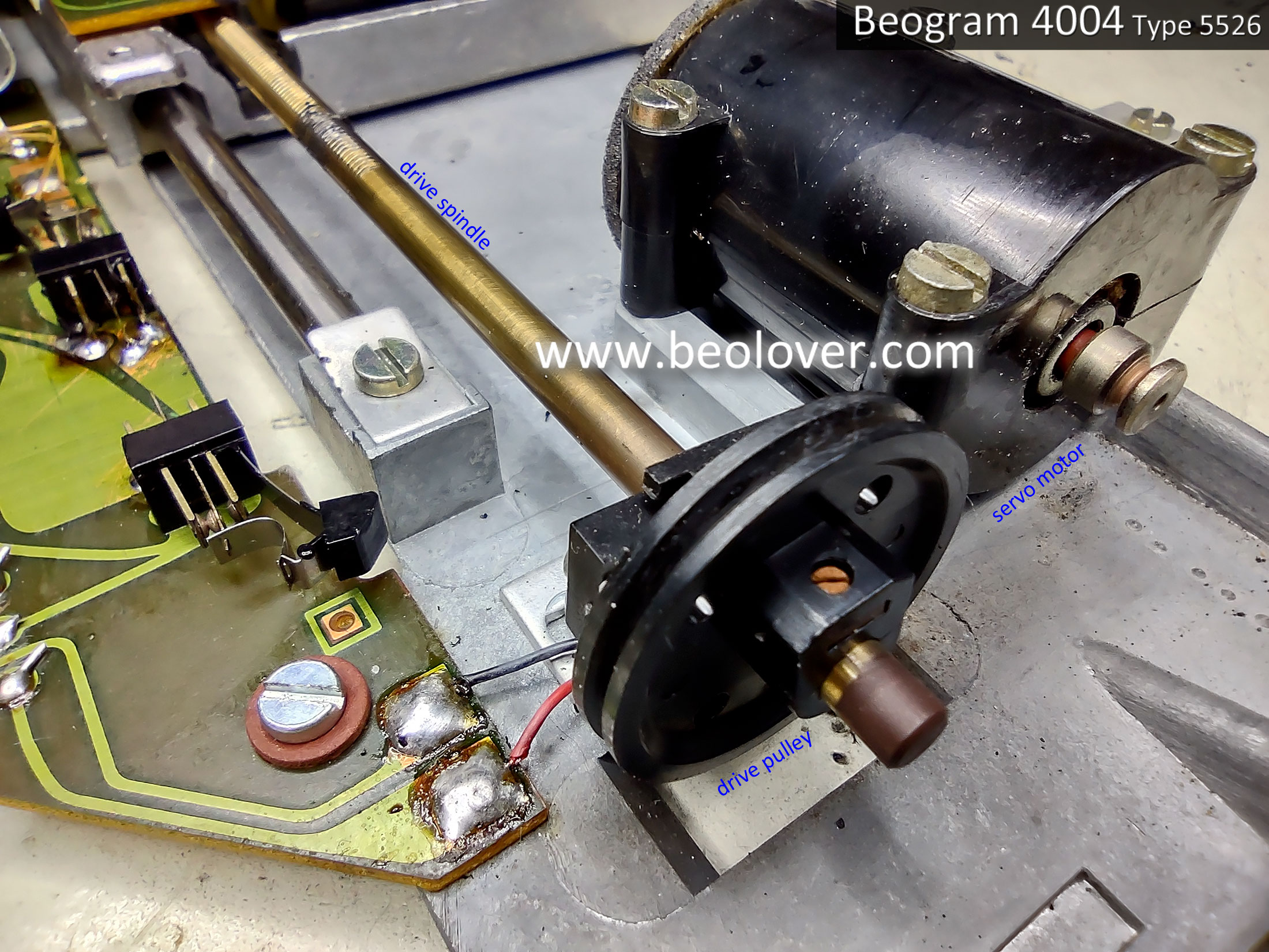


Here is the servo motor opened up.
The foam padding is still intact but pretty brittle. It will eventually completely dry out and start breaking into pieces so I will replace it with new vibration damping material.


I cleaned the spindle with a brush and some alcohol. 
I removed the original, plastic pulley from the spindle and installed an aluminum pulley.


Next, I removed the original tracking sensor lamp assembly to prepare for the installation of the replacement Beolover Beogram 400x tracking sensor lamp assembly.


With the tangential drive spindle removed the tangential arm assembly can easily be slid up and down the two guide rails.  This is a good time to clean them before applying new grease.


That is all I am going to do on the floating chassis components for now.
It is time to move on to the work on PCB 1 and PCB 8.
Once those are complete I will return to the floating chassis to install the new Beolover tracking sensor lamp assembly along with replacing the fixed arm, record detection lamp (also a Beolover lamp assembly).

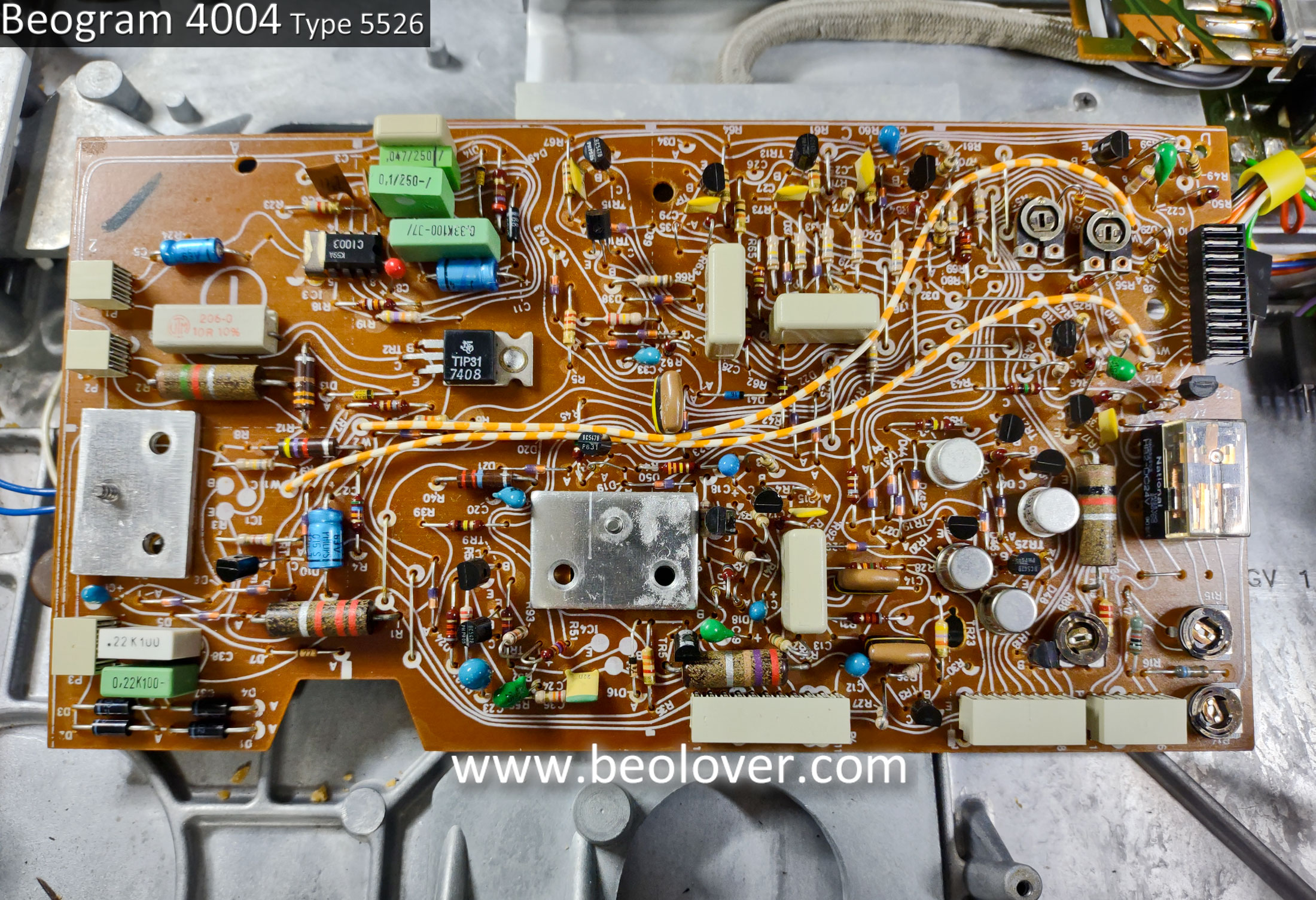
Here is the before photo of the Beogram 4004 Type 5526 PCB 1, the main turntable electronic control circuits.


Here is the PCB 1 after photo...after the capacitor replacement has been done, a new platter speed selection relay has been installed, new trimmers for the platter speed control, new trimmer for the position sensor calibration (1R88), new 1TR3 transistor for the record detection circuit and a corresponding 2MΩ trimmer for calibrating it (in place of the original 1MΩ, 1R26).


Note: As we normally do, the 2MΩ, 1R26 trimmer is installed temporarily on the trace side of PCB 1 so it is accessible when it is initially set (to calibrate 1TR3).  Once the calibration is done, the 1R26 trimmer will be moved to the component side of PCB 1.  You can also see that a WIMA 4.7uF capacitor has been located on the trace side of PCB 1.  That component will stay on the trace side as I don't want any possibility of it physically interfering with the floating chassis mount that sits below PBC 1.
Regarding transistor 1TR3...the original transistor measured with an Hfe below 500 so I installed a new transistor that has an Hfe of above 500.  Together with the 1R26, 2MΩ trimmer there should be no problem adjusting the record detection signal per the service manual.

I also worked on the Beogram 4004 Output circuit board (PCB 8).
The Beogram 4004 Output circuit board has a lot more components than a Beogram 4002 from the same time period (i.e. a Beogram 4002 Type 5523).  The reason for that is the Beogram 4004 has a remote control circuit that ties in with a Beomaster 2400 receiver.  

Here is the before photo of the PCB 8 board.


Here is the after photo.


Things to note on the updated board are the replacement of the muting relay and the addition of a grounding selection switch.

We install this type of switch on all of our Beogram 400x turntable restorations to provide an easily accessible control over the way the signal ground and chassis ground are configured inside the Beogram for the phono cable.  Some phono amplifiers need signal ground and chassis ground tied together or else there is hum on the phono signal.  Other phono amplifiers do not.  The switch makes both options available for the owner.

The project is getting close to actual record play now.

In the next post I will install the new Beolover Fixed Arm Lamp Assembly,  the Beolover Tracking Sensor Lamp Assembly, lubricate the tangential arm assembly and perform the service manual tonearm adjustments.

Sunday, June 12, 2022

Beogram 6000 Type 5502: Initial Assessment, Cleaning and Keypad Restoration

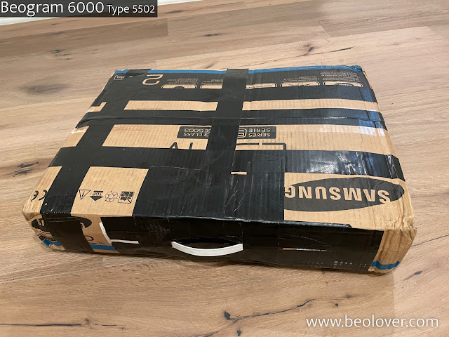
I was fortunate to find a Beogram 6000 type 5502 that was being sold for far too cheap by someone who didn't understand what they had. Unfortunately, despite my linking to the Beolover packaging instructions, they decided to go their own way. This is the second time I have received a Beogram in a 24" monitor box, it would seem to be exactly the right size... if the size of your box is exactly the size of the contents with no padding!


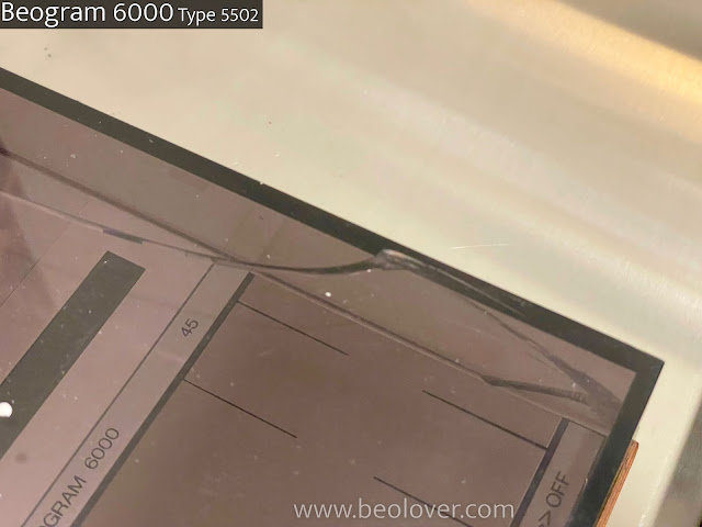
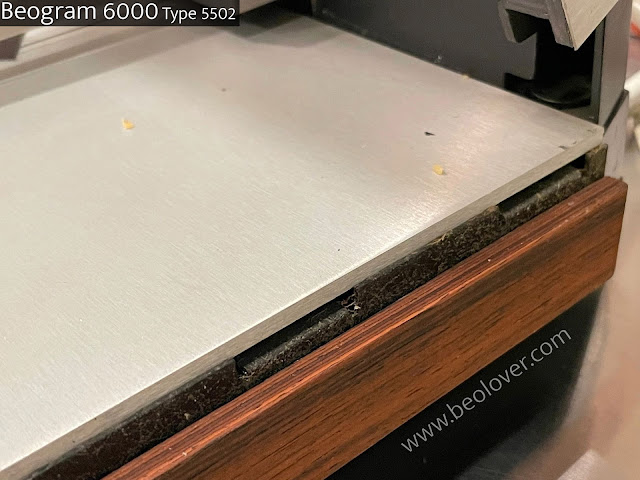
And as such, despite the nifty handle, there was no way it was going to make it from Europe to the US unscathed:


Inside, they did not pack the platter separately, which caused the bearing to pop out of the back of the floating chassis. Gaffer tape is also far too sticky for this:


When carefully removed, it left a residue:


Inside, we have some nicely untouched electronics, even the white plastic parts are perfectly white:


The gem of the 6000 is the output board (shipment also damaged the CD4 switch):


Outside, the paint on the hood back bar was scraped, but fortunately, the rest of the paint is in good condition:


Since this is a type 5502, it has an AC motor with a heavy zinc platter, this early unit has the platter top plate glued to the platter base (rather than 6 screws found in most type 5503's), which is a carryover from the Beogram 4000:


The first step was to extract the keypad and pop the key surface off (these early AC models have a brittle glue that "clicks" apart with a little pressure). The keypad will be restored with the method detailed in this post.


Incidentally, on the back side there was some charring - there may be some component failing on the output board, which will be investigated in future posts:


Here are the keypad plate and plastic pieces, you can see the light finger mark wear on the original clear coat:


I cleared the glue using a flat #17 X-Acto blade (a few scratches this time, but this is covered up in the end!) and then I painted under the keys where the black had worn off:


Here's the back of the keypad after I removed the glue:


I sent the keypad off to be professionally coated. This can take a while, so I moved on to some other cosmetic work while waiting.

After some thorough cleaning, and a replacement wood plinth, I found that this unit is actually in spectacular condition under all the dirt, grime and sticky gaffers tape:


The audio output cable also polished up nicely:


A few weeks later, the keypad top plate is back from being coated and can be carefully glued to the keypad frame:


And now we have a beautiful exterior cosmetic restoration:


The next steps will be completed by Sonavor, including capacitor replacement and all the service manual procedures for electronic and mechanical adjustment, after which it will become a part of his personal collection.


Saturday, June 11, 2022

Beogram 4004 Type 5526: A Local Beogram 4004 Project Continues (Finally)

It is time to get cracking on a delayed Beogram 4004 project.
I initially assessed this Beogram 4004 back on this January 2022 post.
A bunch of delays ensued but now things can get moving again.

I disassembled the Beogram 4004 to begin work on the various components.

Here is the PCB  1 board shown with its four mounting screws highlighted.


Here is PCB 1 removed.  The main circuit board, PCB 1, looks in great condition so I will start on the restoration of this board in the next post.


Next in line for the disassembly is the Beogram keypad.
This keypad is in really nice shape for an original keypad. There are some minor scuffs and with the light held just right, you can see some signs of where fingers operated the controls.


The underside of the keypad shows the typical tarnished button contacts. I will clean those thoroughly and coat them with some Deoxit contact cleaner.


With the keypad removed I can get to the Beogram 4004 Output/Remote Control board (PCB 8).
The PCB 8 board contains the phono mute relay and is where the audio signal transitions from the tangential arm assembly chassis to the phono cable that carries the audio signal to an external preamp.

Here is PCB 8 from this Beogram 4004 unit.


PCB 8 is a board that is in all Beogram 4002/4004 turntables. All of the types have the Phono Audio Output and Mute circuit.  The rest of the PCB 8 board is for additional circuits that various Beogram 400x types can have.

For example, the Beogram 6000 has 4-Channel decoding circuitry on its Output Board.
The Beogram 4002 Type 5523 only has the muting circuit and nothing else.
This Beogram 4004 has a remote control circuit that integrates with the remote control of the Beomaster 2400 receiver.  Of course nowadays we have the Beolover Commander Remote Control. :-)

After PCB 1, PCB 8 and the control keypad components are out of the way, the Beogram 4004 floating chassis can be removed from the cabinet base.

This photo shows a section of the cabinet with one of the lockdown mechanisms for the floating chassis.  There are three of these lockdown mechanisms and each one must be disassembled to remove the floating chassis.  The original Beogram 4004 would have had rubbery, plastic bushings around the lockdown plates.  As is very common, the original bushings became hard and brittle...to the point where they just broke into pieces.


The following photos show the disassembly of the top part of the floating chassis lockdown mechanism.  


This picture shows a lone piece of the original lockdown bushing.  That is where the bushing was located before it deteriorated and broke apart.


Here is the lockdown mechanism after the floating chassis has been removed.


Here is the removed Beogram 4004 floating chassis assembly.
Highlighted in the photo is the actuator of the Beogram ES switch. It was floating around in the cabinet.


The tonearm assembly looks really great on this Beogram 4004 unit. The arm lowering works nice and the components look to be aligned properly.


The servo motor and pulley look okay and do function.
The original plastic pulley is in good shape but does have the start of a small crack.
The internal vibration damping material of the servo motor is showing signs of age. The foam material eventually crumbles and becomes dust.


Here is a picture of the SO and ES switches of the Beogram tangential arm assembly.
The ES switch is broken and the SO switch looks pretty worn too.


Here is what two intact SO and ES switches should look like.


I will have to find a couple of replacement switches for the ES and SO switch.

Last, here is a look at the tonearm assembly lowering and raising mechanism.  It is in great shape as I mentioned earlier.


After this Beogram disassembly I can update my assessment of the restoration.

The recapping and replacing of components on the circuit boards doesn't appear to have any surprises.
I have all of the parts I need so those tasks can begin right away.

The keypad just needs some cleaning of the switching contacts.

The floating chassis needs new lockdown bushings.

The servo spindle pulley may need replacing with a new aluminum pulley.  I will further evaluate the condition of the plastic pulley.

I will also check the servo motor vibration damping material to see if it needs new material.

The ES and SO switches need replacing. I should be able to source those myself.

On to the circuit board work ...