A common failure on the Beomaster 1900 and 2400 receivers is with the tone control slider assemblies. Each slider has a left and right channel contact that slide up and down together on a plastic bridge. The contacts are press fitted onto the bridge and held by a plastic post and bar. Over time the plastic bar breaks and the contact comes loose. That results in the slide control no longer working.
Martin Olsen on Beoworld makes replacement slider bridge kits specifically for the Beomaster 1900 and 2400 units. I have used his kit on all of my Beomaster 1900 restorations so far and will continue with this Beomaster 2400 unit. The replacement bridge parts have a beefier bar for the contacts to mount to than the original part.
Here are each of the three tone control sliders disassembled from the tone control board starting from left to right with the Bass slider first.
As you can see the Bass slider has the usual broken tab but it also has a problem where one of the contacts is missing. I did not see it anywhere in the Beomaster cabinet so it is long gone. Fortunately I have a spare.
Next is the Treble slider.
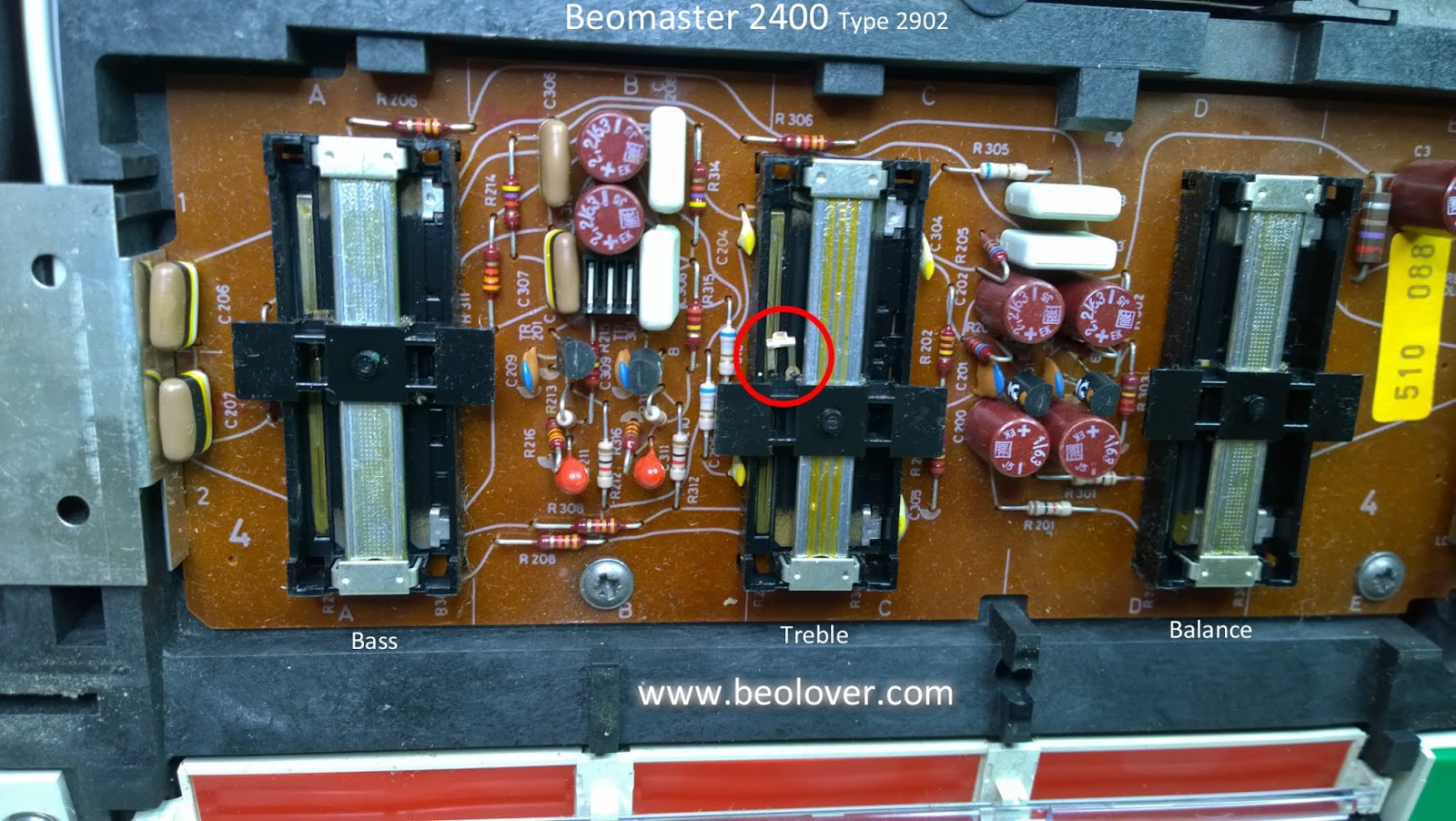
Both left and right channel contacts are present with the Treble slider but its slider bridge tabs are broken.
Last is the Balance slider.
The Balance slider has its slider bridge all intact. I will still replace it along with the Bass and Treble sliders as this slider control is likely to break in the future. Martin's repair kit comes with three replacement bridges so I will use all of them.
Besides replacing the slider bridge I clean the metal contacts and the rails.
The repair for all three slider control bridges is the same so I will just show one in detail here.
...and here are all three slider controls re-installed on the Beomaster 2400 Tone Control board.
Featured Post
Beolover SyncDrive: DC Platter Motor Replacement for Beogram 4002 and 4004 (Type 551x and 552x)
Late Beogram 4002 and the 4004 (Types 551x and 552x), which have DC platter motors instead of the earlier synchronous AC motors usually suff...
Tuesday, July 9, 2019
Monday, July 8, 2019
Beomaster 8000 - Workbench Unit - Testing a replacement device for the AD 10/192 Multiplex Switch on the preamplifier board
To go together with the previous Beomaster 8000 replacement part for the preamplifier source switching device (AD 10/278 - 3IC102/3IC202), I have completed the replacement part for the other switching device on the preamplifier board.
The second source switching device is 3IC4. The original device is an AD 10/192 multiplexer and like the other switching ICs, this device is no longer available.
Here is the schematic diagram again that shows the two source switching type devices in the Beomaster 8000 preamplifier.
The 3IC102 and 3IC202 replacements were completed earlier. Now it is time for the 3IC4 device.
Like the the other replacement I first built a prototype and tested it in my Beomaster 8000 workshop test unit. It worked as good as I expected so I had an adapter board made.
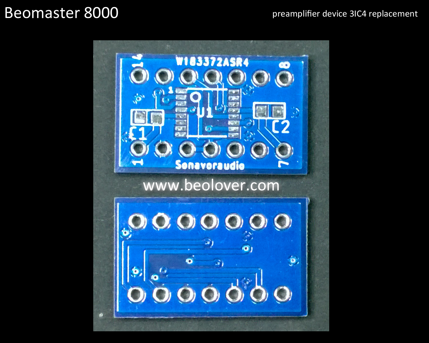
Here is the replacement switching device on the new adapter board next to my prototype.
...and here is the first replacement device unit installed in the Beomaster 8000 preamplifier.
The Beomaster 8000 preamplifier works great with the source multiplexing devices replacements.
Now to the fun listening test phase.
The second source switching device is 3IC4. The original device is an AD 10/192 multiplexer and like the other switching ICs, this device is no longer available.
Here is the schematic diagram again that shows the two source switching type devices in the Beomaster 8000 preamplifier.
The 3IC102 and 3IC202 replacements were completed earlier. Now it is time for the 3IC4 device.
Like the the other replacement I first built a prototype and tested it in my Beomaster 8000 workshop test unit. It worked as good as I expected so I had an adapter board made.
Here is the replacement switching device on the new adapter board next to my prototype.
...and here is the first replacement device unit installed in the Beomaster 8000 preamplifier.
The Beomaster 8000 preamplifier works great with the source multiplexing devices replacements.
Now to the fun listening test phase.
Labels:
2019SVRBM8000-01,
3IC4,
AD 10/192,
analog switch,
Bang & Olufsen,
bench test,
Beomaster 8000,
preamplifier,
replacement part,
restoration,
sonavoraudio,
test unit,
testing,
trouble-shooting,
workbench
Sunday, July 7, 2019
Beomaster 2400 Type 2902: Recapping the tone control board and FM tuner
To wrap up the capacitor replacement on this Beomaster 2400 restoration there is just one capacitor in the FM tuner box and a handful of capacitors on the tone control board.
The FM tuner box has top and bottom lids that must be removed. There is a shield wire that must be desoldered from the bottom lid before it can be opened. The bottom lid is necessary to desolder the lone 10uF capacitor leads.
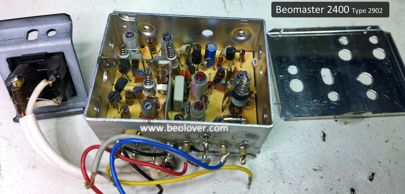
Under the top lid we can find the capacitor that will be replaced.
...and here is the recapped version
The last board to recap is the control board for the tone controls and FM tuning. There are just ten capacitors to replace. Here is the before and after picture.
I am not finished with this tone control board yet. The next task is to remove the Bass, Treble and Balance slide control devices to rebuild them.
The FM tuner box has top and bottom lids that must be removed. There is a shield wire that must be desoldered from the bottom lid before it can be opened. The bottom lid is necessary to desolder the lone 10uF capacitor leads.
Under the top lid we can find the capacitor that will be replaced.
...and here is the recapped version
The last board to recap is the control board for the tone controls and FM tuning. There are just ten capacitors to replace. Here is the before and after picture.
I am not finished with this tone control board yet. The next task is to remove the Bass, Treble and Balance slide control devices to rebuild them.
Saturday, July 6, 2019
Beomaster 2400 Type 2902: Recapping the main board and the volume control board
I completed the capacitor replacement on the Beomaster 2400 main board and volume control board. This included replacing the reservoir capacitors and the idle current adjustment trim pots for both channels.
The Beomaster 1900 and 2400 receivers are not my favorite units to replace capacitors on. They are very compact and low profile which make things a little cramped inside. Unlike the large Beomaster 8000 these smaller Bang & Olufsen receivers do not have easy accessible and removable circuit boards for working on.
Here is another picture for the Beomaster 2400 before the main board recapping.
You can see there are a lot of capacitors to change out. About eighty capacitors out of the ninety-nine total I will be replacing. I can't easily disconnect the main board from the rest of the Beomaster 2400 to remove it for recapping as it has several hard-wired connections to the transformer and power supply. On a Beomaster 1900 one time I removed everything from the cabinet chassis but that still made maneuvering the board awkward as I had the weight of the still connected transformer to deal with.
Since then I like to disconnect the FM tuner box, reservoir capacitors and heatsinks so I can switch from front and back of the main board while recapping.
I remove a couple of solid wires to the transformer to avoid breaking them while working on the main board.
After that it is a careful and tedious ordeal of desoldering and soldering while switching from the component side of the board to the trace side...back and forth. This is another picture of the main board after the recapping work was completed.
There was one 10uF, 63VDC capacitor under the metal shield box for the remote control circuit.
I usually replace capacitors with values of 4.7uF and smaller with WIMA MKS capacitors.
An exception is if the WIMA won't fit well as with the two small 4.7uF capacitors on this small B&O adapter board.
This picture shows the two Beomaster 2400 idle current trim pots after I replaced the originals.
When installed back in the cabinet frame the emitter resistors are difficult to attach probes to for making the idle current (or no-load current) adjustment. While I have the main board in service position I like to make sure the leads on the emitter resistors are long enough on the trace side of the board to clip measurement probes to.
This picture shows the +15VDC supply reservoir capacitor after the recap. I used a little bit of Aleene's glue to secure it in place.
The two large 5000uF reservoir capacitors are kind of a pain to change out on these types of Beomaster units. The original capacitor terminals are soldered together as well as all of the connected wires.
In my replacement reservoir capacitor assembly I use small terminal connectors to attach the wires to the capacitors and the two capacitors to each other.
That is a more secure connection and makes future desoldering of the reservoir capacitors easier.
The small volume control board only has six small capacitors to replace.
That leaves one capacitor in the FM tuner box to replace and a few capacitors on the tone control and FM tuning control board. Then the recap work will be complete.
The Beomaster 1900 and 2400 receivers are not my favorite units to replace capacitors on. They are very compact and low profile which make things a little cramped inside. Unlike the large Beomaster 8000 these smaller Bang & Olufsen receivers do not have easy accessible and removable circuit boards for working on.
Here is another picture for the Beomaster 2400 before the main board recapping.
You can see there are a lot of capacitors to change out. About eighty capacitors out of the ninety-nine total I will be replacing. I can't easily disconnect the main board from the rest of the Beomaster 2400 to remove it for recapping as it has several hard-wired connections to the transformer and power supply. On a Beomaster 1900 one time I removed everything from the cabinet chassis but that still made maneuvering the board awkward as I had the weight of the still connected transformer to deal with.
Since then I like to disconnect the FM tuner box, reservoir capacitors and heatsinks so I can switch from front and back of the main board while recapping.
I remove a couple of solid wires to the transformer to avoid breaking them while working on the main board.
After that it is a careful and tedious ordeal of desoldering and soldering while switching from the component side of the board to the trace side...back and forth. This is another picture of the main board after the recapping work was completed.
There was one 10uF, 63VDC capacitor under the metal shield box for the remote control circuit.
I usually replace capacitors with values of 4.7uF and smaller with WIMA MKS capacitors.
An exception is if the WIMA won't fit well as with the two small 4.7uF capacitors on this small B&O adapter board.
This picture shows the two Beomaster 2400 idle current trim pots after I replaced the originals.
When installed back in the cabinet frame the emitter resistors are difficult to attach probes to for making the idle current (or no-load current) adjustment. While I have the main board in service position I like to make sure the leads on the emitter resistors are long enough on the trace side of the board to clip measurement probes to.
This picture shows the +15VDC supply reservoir capacitor after the recap. I used a little bit of Aleene's glue to secure it in place.
The two large 5000uF reservoir capacitors are kind of a pain to change out on these types of Beomaster units. The original capacitor terminals are soldered together as well as all of the connected wires.
In my replacement reservoir capacitor assembly I use small terminal connectors to attach the wires to the capacitors and the two capacitors to each other.
That is a more secure connection and makes future desoldering of the reservoir capacitors easier.
The small volume control board only has six small capacitors to replace.
That leaves one capacitor in the FM tuner box to replace and a few capacitors on the tone control and FM tuning control board. Then the recap work will be complete.
Monday, July 1, 2019
Beomaster 2400 Type 2902: Another restoration project begins
An owner of a Beomaster 8000 restoration I did last year sent me a nice Beomaster 2400 unit that needs some work. Today I was finally able to put it on the bench and check out what condition it was in.
The outside cosmetic condition of this Beomaster 2400 is quite nice. With it plugged in I can get sound from the FM tuner testing the Beomaster output with some headphones. I can see however that the Treble indicator lamp is burned out. In addition, the Bass and Treble controls do not work. The slide control knobs are loose which is a symptom of broken sliders.
As you can see, a handsome Beomaster 2400 unit. It didn't arrive with a remote control so I used mine to check that the remote control functionality works...it does.
Now it is time to open the Beomaster up. I know that it partially works so that is good. However, the problems it shows from the initial testing indicate that typical problems for this receiver exist.
The disassembly begins by removing screws on the underside of the Beomaster. I have circled the screws that I remove with red circles in the pictures.
This is an early production Beomaster 2400 unit. The Phono DIN jack is the 5-pin type of DIN jack. Later Beomaster 2400 units were fitted with 7-pin DIN jacks to go along with the added support of remote control functionality of the Beogram 4004 turntable. Bang & Olufsen produced a modification kit that included a 7-pin DIN jack and wires to add the Beogram 4004 remote control support to these early models.
Here is the schematic diagram from that mod kit.
We will decide later in this restoration whether this mod kit will be applied. Interestingly, there are 7-pin DIN jacks available for the Beomaster 2400 from later model Beomaster 1900 units. Because the Beomaster 1900 and 2400 share the same main board Bang & Olufsen started installing 7-pin DIN jacks on both the Beomaster 2400 and the Beomaster 1900 units...even though the BM1900 receivers do not have remote control circuitry. Swapping a 5-pin DIN jack from an early Beomaster 2400 with a 7-pin DIN jack from a later model Beomaster 1900 would not result in loss of functionality for either unit.
Continuing on with the Beomaster 2400 disassembly I loosened the rear panel for removal.
That step allows the bottom panel that was loosened earlier to now be removed.
Next is the removal of the tone control and FM tuning control panel. Two screws are removed on either end of the panel to allow it to slide out.
Now for removal of the bottom control panel (volume control and source selection).
With the control panels removed I can see the inside components of the Beomaster 2400. I spot some problems with the Bass and Treble tone controls as well as with the display indicator masks for Bass, Treble and Balance.
The indicator masks have started to deteriorate from the heat produced by the indicator lamps. I have seen this before on the Beomaster 1900 (which as I said before, is essentially the same receiver...minus remote control).
I have new replacement masks I can fix the deteriorating ones with. In this restoration I will also change the Bass, Treble and Balance display lamps to LED lamps which run way cooler and should not repeat this problem.
Be careful removing the little brass clips that hold the display mask to the slider bridge. If done wrong the lip of the brass clip can easily be broken off. The ends of the clips need to be pressed inward then up as shown here.
The Bass and Treble adjustment sliders are loose and do not function. This is usually because small, plastic clips on the plastic slider bridges have failed. I can see that is the case here. Martin Olsen produces replacement bridge parts to fix this problem so I will be installing those here.
To continue the disassembly of the Beomaster 2400 I need to loosen and remove the tone control and tuner control board followed by the removal of the three indicator lamp modules (volume, tone control and source selection).
Now all that is left is to loosen the large, main board so I will be able to get to the majority of capacitors that need replacing in this restoration project.
The FM tuner box (the shiny silver box) and the FM antenna jack must also be loosened.
Finally the main board can be lifted up for access to all of its components.
I can also get to the two reservoir capacitors easily now for replacement of those.
The initial evaluation is complete on this unit and the Beomaster 2400 is opened up where restoration work can begin.
The outside cosmetic condition of this Beomaster 2400 is quite nice. With it plugged in I can get sound from the FM tuner testing the Beomaster output with some headphones. I can see however that the Treble indicator lamp is burned out. In addition, the Bass and Treble controls do not work. The slide control knobs are loose which is a symptom of broken sliders.
As you can see, a handsome Beomaster 2400 unit. It didn't arrive with a remote control so I used mine to check that the remote control functionality works...it does.
Now it is time to open the Beomaster up. I know that it partially works so that is good. However, the problems it shows from the initial testing indicate that typical problems for this receiver exist.
The disassembly begins by removing screws on the underside of the Beomaster. I have circled the screws that I remove with red circles in the pictures.
This is an early production Beomaster 2400 unit. The Phono DIN jack is the 5-pin type of DIN jack. Later Beomaster 2400 units were fitted with 7-pin DIN jacks to go along with the added support of remote control functionality of the Beogram 4004 turntable. Bang & Olufsen produced a modification kit that included a 7-pin DIN jack and wires to add the Beogram 4004 remote control support to these early models.
Here is the schematic diagram from that mod kit.
We will decide later in this restoration whether this mod kit will be applied. Interestingly, there are 7-pin DIN jacks available for the Beomaster 2400 from later model Beomaster 1900 units. Because the Beomaster 1900 and 2400 share the same main board Bang & Olufsen started installing 7-pin DIN jacks on both the Beomaster 2400 and the Beomaster 1900 units...even though the BM1900 receivers do not have remote control circuitry. Swapping a 5-pin DIN jack from an early Beomaster 2400 with a 7-pin DIN jack from a later model Beomaster 1900 would not result in loss of functionality for either unit.
Continuing on with the Beomaster 2400 disassembly I loosened the rear panel for removal.
That step allows the bottom panel that was loosened earlier to now be removed.
Next is the removal of the tone control and FM tuning control panel. Two screws are removed on either end of the panel to allow it to slide out.
Now for removal of the bottom control panel (volume control and source selection).
With the control panels removed I can see the inside components of the Beomaster 2400. I spot some problems with the Bass and Treble tone controls as well as with the display indicator masks for Bass, Treble and Balance.
The indicator masks have started to deteriorate from the heat produced by the indicator lamps. I have seen this before on the Beomaster 1900 (which as I said before, is essentially the same receiver...minus remote control).
I have new replacement masks I can fix the deteriorating ones with. In this restoration I will also change the Bass, Treble and Balance display lamps to LED lamps which run way cooler and should not repeat this problem.
Be careful removing the little brass clips that hold the display mask to the slider bridge. If done wrong the lip of the brass clip can easily be broken off. The ends of the clips need to be pressed inward then up as shown here.
The Bass and Treble adjustment sliders are loose and do not function. This is usually because small, plastic clips on the plastic slider bridges have failed. I can see that is the case here. Martin Olsen produces replacement bridge parts to fix this problem so I will be installing those here.
To continue the disassembly of the Beomaster 2400 I need to loosen and remove the tone control and tuner control board followed by the removal of the three indicator lamp modules (volume, tone control and source selection).
Now all that is left is to loosen the large, main board so I will be able to get to the majority of capacitors that need replacing in this restoration project.
The FM tuner box (the shiny silver box) and the FM antenna jack must also be loosened.
Finally the main board can be lifted up for access to all of its components.
I can also get to the two reservoir capacitors easily now for replacement of those.
The initial evaluation is complete on this unit and the Beomaster 2400 is opened up where restoration work can begin.
Subscribe to:
Posts (Atom)