Featured Post

Beolover SyncDrive: DC Platter Motor Replacement for Beogram 4002 and 4004 (Type 551x and 552x)

Late Beogram 4002 and the 4004 (Types 551x and 552x), which have DC platter motors instead of the earlier synchronous AC motors usually suff...

Wednesday, February 6, 2019

Beogram 4004 Type 5526: Last minute mod on the Beogram 4004 Turntable #1 from Dallas

The Beogram 4004 turntable number one (of two) from Texas was ready to return home to its owner when a special modification was requested. The owner has a modern integrated Bang & Olufsen system from the late nineties (Beocenter 2500) that is now the intended receiver for this Beogram. That presents a problem because the modern systems do not come with a built-in RIAA preamplifier which is required to prepare raw phono cartridge signals for amplification. The resurgence in the popularity of vinyl records has meant a whole bunch of amplifier systems out there without support for phonographs.

There are quite a few third party solutions of course. Those involve a small RIAA preamplifier box between the turntable and the modern amplifier. That works quite nicely but there is a better way when it comes to a Beogram 4002 or 4004 turntable.

Beolover has designed and built a custom Beogram 4002/4004 RIAA amplifier board that connects right into the Beogram (on the existing output board).


The beauty of this design is two-fold.

1. The modification is internal to the Beogram so it doesn't require an external box and additional cables. The original phono cable is used as-is.

2. The modification retains the original connections so the Beogram can still be used with amplifiers that have their own RIAA preamplifier.

The installation of the Beolover RIAA preamp is quite easy.  Here is the sequence.


In most cases the installation is just to remove the phono output muting relay and solder in the custom RIAA preamp board. For this case I also had to remove the grounding option switch I had installed earlier in the project.

The grounding option is not necessary when using the RIAA preamp connectors. If the owner wants to change the receiving amplifier for this Beogram later, to one that has an RIAA preamp, then the grounding option is still nice to have.  The switch I had installed before would be in the way so it has been replaced with a simple two-pin jumper between signal ground and system ground.

Here is the Beogram 4004 output board with the new RIAA preamp mod re-installed.
This picture shows the board connected up for use as the original Beogram....without any RIAA preamplifier.  I want to test that the original functionality works first.  Then I will switch it to use the Beolover RIAA preamp connectors and test the Beogram in that configuration.


If any other Beogram 4002/4004 owners would like to try this preamplifier for their Beogram just contact Beolover at beolover@gmail.com.

Tuesday, February 5, 2019

Beogram 4004 (5526): Repair of Record Detection Circuit and a New Reservoir Capacitor

I started working on the Beogram 4004 that I recently received. I decided to look into the 'does not lower arm at LP set-down point' issue first.

***I recommend downloading the Beogram 4002/4 service manual with the circuit diagram for reading this post.***

Usually, when a 400x Beogram does not stop at the LP point after pressing START (with a record on the platter), there are two standard causes:
1) It does not detect the record properly, or
2) the carriage position sensor does not work.

#2 is easily eliminated by watching if the deck switches to 45 RPM once the arm sweeps past the 7" singles setdown point. If it does, the position sensor is most likely up to the task.

The 4004 did the 45 RPM switch, i.e. it was time to look into the record detection circuit. The record detection circuit essentially needs to pass three tests:

1) Does the light bulb in the sensor arm work, and is it the correct bulb with the right current draw?

2) Does the platter induce a proper ~5.5-6V amplitude signal at the collector of TR3?

3) Does the circuit put out the proper signal at the collector of TR6 (~15.5V when there is a record; ~0V when there is none) when a record is on the platter?

Since the light bulb was working (lit B&O logo), I measured the voltage at the Collector of TR5 that drives the bulb and it showed 8.5V (spec is 9V, but that is o.k.). This voltage is used by the circuit to put out a 'no record present' signal when the bulb is dead (the voltage would be close to 21V in that case, which would permanently turn on TR6, i.e. its collector would be 0V - saying 'do not lower the arm'. This is a safety feature, since without it a dead bulb would give the sensor the same impression as the presence of a record, and the arm would be lowered on the platter.

With regard to #2, it is a good idea to check the DC voltage at the collector of TR3 first and measure if it is close to the prescribed 4V. This voltage is necessary to ensure that the sensor signal has a 6V amplitude when the ribs of the platter pull by beneath it. I measured 2.1, which was very low. This meant I needed to replace the biasing resistor R26 with a 2M trimmer for adjusting the bias of TR3 (in essence quench some of the CE current to achieve a higher C voltage). This is a very common issue in the 400x, and implanting the trimmer usually allows adjusting the bias to get 4V at the collector. I put in the trimmer and tried to adjust the collector voltage:
Unfortunately, even by completely maxing out the 2M resistance on the trimmer, I was only able to get to 3.4V. This meant that TR3 had an unusually large Hfe. In absence of an even larger trimmer (and the rule of thumb not to use large resistances/very small currents in such circuits if one can avoid it) I decided to put a new BC547B transistor in. This fixed it:
I measured the Hfe values of both transistors, and the original 548C had about 750, while the Hfe of the new one was only 430, which allowed the 2M trimmer to do its job.

While it was a good idea to fix the TR3 voltage, this was unlikely to have fixed the issue, since a too small sensor signal causes the opposite effect: It always detects a record whether there is one or not, i.e. the arm gets lowered onto the platter if there is an issue with the sensor signal.

The next step was to check on the output of the detection circuit, i.e. I needed to measure the voltage at the collector of TR6 when the carriage reached the setdown point. I did, and the voltage remained close to 0V, indicating that the circuit was not doing its job. First I thought TR6 was bad, but my transistor tester gave it a passing score. This meant something else was pulling the voltage down to zero.

I started the Beogram without TR6 in place. This essentially should tell the circuit "record present" since this causes the same situation like a turned off TR6. I measured the voltage again at the vacant collector terminal of TR6...and it was close to 0 volt again! So clearly there was a short somewhere. The most direct connection to 0V is probably via a shorted out C19 that would pull the collector pad down to ground via R41. I measure the capacitance of C19 in situ with my BK Precision 879B LCR meter, and it yielded 4.7 Ohms! This caused me a bit of head scratching, since there is essentially no other good path for this short circuit to happen in this circuit. I finally measured the resistance across C19 with my multimeter, and I got a stable reading of 132 Ohm! That should not happen with a working capacitor. So I took the capacitor out and replaced it with a new one. And the circuit worked again.

I thought this capacitance measurement was an interesting lesson. I measured the cap with my multimeter's capacitance setting, and it showed 0F. So it seems that the frequency based measurement method has hits weaknesses, when it comes to measuring borderline dead capacitors. The 879B did show an ESR value of 11 Ohm on this capacitor, which is very high. This should have tripped me off right away, but in the fog of battle...anyway, an enjoyable evening with a Beogram 4004 is coming to an end!...;-).

But wait, this Beogram had one more issue to rectify: The reservoir capacitor. Whoever tried to fix it before hot-wired a new reservoir cap of the cheapest kind into the unit:
I replaced it with a Beolover capacitor assembly that fits precisely under the mounting strap of the original one:
Beolovely again!


Beomaster 8000 From Canada: Packing for shipment home

The day finally arrived to ship the Beomaster 8000 from Canada back home. All tests have passed and loose end tasks completed.

This receiver is quite heavy. The packed shipping weight can be from 57 pounds to 65 pounds depending on packing materials. I was able to get this shipment prepared at 57 pounds in a 30 inch x 20.5 inch x 12 inch box.

I glue the bottom flaps of the cardboard box together with a common wood glue.
After that I lined the bottom and sides with 1 inch thick, 2.2 pound rated, polyethylene foam. Those pieces are attached using 3M Super 77 spray adhesive. Polyethylene foam has some give to it but is sturdy enough to resist puncture. A good material for the first line of defense.


The old type styrofoam and styrofoam peanuts are the absolute worst packing material ever devised. They should never be used!
They generate a lot of static electricity and small pieces get into everything...especially the audio component you are shipping.

Bubble wrap is not very good either. It is okay for small, light things but heavy shipments can puncture the bubble wrap leaving no protection at all.

For this Beomaster 8000 my first step in wrapping it up for placement in the shipping box is to place it inside a clear plastic bag. That will protect against any liquid and keep packing materials from rubbing directly against the Beomaster.


Next I use 1½ inch thick eggcrate foam to wrap the Beomaster providing another layer of padded protection. This foam has more cushion than the polyethylene outer foam. I do one wrap lengthwise and one wrap crosswise.


The eggcrate foam wraps are taped and everything is placed into the shipping box. I use extra blocks of the polyethylene foam to fill in any gaps.


The last rectangular piece of polyethylene foam is the lid followed by taping shut the cardboard box.


This Beomaster 8000 receiver is now on its journey back home and I hope to hear happy results from the owner after it arrives.

Beomaster 1900 Type 2904: Preparing for recapping tasks

The Beomaster 1900 project continues with preparing the circuit boards for recapping. I don't like carefully navigating between wires and components to replace capacitors. My technique is to disassemble the Beomaster so I can easily get to the components I need to work with. On these vintage receivers I always reflow the solder joints on connectors so that is another reason to have clear access to everything on the boards.

The previous Beomaster 1900 project post left off with the receiver opened up for inspection. As I got ready to remove the tone control and FM tuning board I inspected the three slider controls a little closer. Several of the slide contacts are loose indicating this unit will need Martin's slider control repair kit.


The Bang & Olufsen engineers designed this compact assembly so the boards can be accessed pretty easy. The tone control and FM tuning control board unscrews, tilts up and lifts out (after disconnecting three connecters).


The lamp housings just unscrew and come out after releasing their plastic spring tabs.


That leaves the main board to get access to. The main board has screws that have to be removed plus the FM antenna connection panel and the FM tuner box. When those are all unbolted the main board can be lifted up from the right side towards the transformer on the left.

I tilt the Beomaster on its side with the transformer end down. That gives good access to everything on the main board.


Interestingly the middle area of the main board has holes and markings for circuitry that is not there.
That is because the Beomaster 1900 and Beomaster 2400 share the same main board but only the Beomaster 2400 has remote control capability.


Now it is time to start replacing the capacitors on this receiver.

Sunday, February 3, 2019

Beogram 4004 (5526): A New Arrival from El Paso - First Look

A Beogram 4004 (5526) arrived from El Paso in Texas for some TLC. It arrived in a custom Beolover made shipping box that had been dispatched to the customer prior to shipping, simplifying the packaging process. The unit arrived in good condition. HD foam and double boxing has never failed the Beolover so far. Check out our 4002/4 page for a video how to package a Beogram properly.

I took the Beogram out of the box and had a first look: The aluminum panels are in pretty good condition (an important starting point for a successful restoration)
Unfortunately the platter has a scratch in the center:
but otherwise it is in good condition.
The hood has the usual scratches from careless storage:
Luckily there is not much damage on the inside, i.e. this hood can be polished back to a nice look.

I took the aluminum panels out and had a look below deck:
The unit seems mostly original except a very unprofessionally installed new reservoir capacitor:
Whoever did this did not even bother to tape it in place, almost ensuring a short circuit down the road  if the unit had been moved while plugged in. Not very Beolovely!

After making sure the capacitor leads would not touch anything, I plugged the Beogram in and pressed start. The carriage started moving, but did not stop at the LP setdown point, indicating an issue with the position sensor. At the same time the platter motor came alive with a shriek, suggesting dry bearings. Most Beograms with DC motor have this issue at this point in time.

In summary, this unit is a good starting point for a restoration, and I am looking forward to playing some nice vinyls on it when it is back in prime condition!


Tuesday, January 29, 2019

Beomaster 1900 Type 2904: New Project From the East Coast

It is time to switch my workbench from Beomaster 8000 and Beogram turntable mode to Beomaster 1900 and 2400 restoration mode.

First is a Beomaster 1900 Type 2904 receiver. The 1900 was a very popular receiver for Bang & Olufsen and was produced from 1976 to 1982. I remember seeing them in the local audio shop (I'm dating myself) and was impressed by their modern touch buttons. That was quite something back then. Of course that went along with the super low profile, sleak Jacob Jensen design. A really nice design that held up with time. It is not surprising that so many owners still want them working today. However, at over forty years old some restoration is required.

That is what the task is with this one. This Beomaster 1900 is in decent physical shape. It needs a little cleaning and polishing. The rosewood veneer trim has some places where it is coming loose. I will have to be careful with those and see if I can save it.


Looking at the bottom side of the Beomaster I see that all four rubber feet are missing.  It looks like Martin Olsen is carrying remanufactured replacements for those so I will be placing an order for those.

I was a little leary about what I would find when I opened up the cabinet. In carrying the Beomaster to the workshop I could hear rattling inside.


Fortunately the rattle was just from pieces of the broken feet. The rubber material is quite deteriorated.


Peeling back the rest of the Beomaster 1900 first layer showed nothing to indicate there are any major problems. I was glad to see that the plastic masks for the bass, treble and balance indicators all look good on this unit. The previous Beomaster 1900 I restored was a Type 2903 and the indicator masks had started to deteriorate from the heat of the illuminating lamps. I have printed replacement masks but those won't be needed on this unit.


Quite a nice unit. Definitely worth getting back to working order.

I will continue to disassembly the Beomaster so I can clean and get to all of the electrolytic capacitors that will be replaced. I will change out the lamps. The volume indicators and FM tuning indicators will get new incandescent lamps as their properties play into the circuit function. The bass, treble, balance and source selection indicators will be switched to LED replacements.

The bass, treble and balance slide pots will be cleaned and lubricated. A common failure in these receivers are the plastic mounts for the slide control contacts so I will check that those are good. If not I have Martin's repair kit for them.

Sunday, January 27, 2019

Beomaster 8000 From Canada: Taking care of some loose ends before shipping home

The Beomaster 8000 receiver from Canada that I blogged about here has been undergoing extensive testing in my listening room.  The input sources (FM, phono, tape 1 and tape 2) have been exercised for countless hours. This unit has performed great.

When it was time to unplug the Beomaster from my Beosystem 8000 listening room setup I got a surprise when I unplugged the Beogram 8000 cable. The Beomaster 8000 Phono DIN jack came out with. Part way anyways. The wires in the Beomaster source input connector box kept the DIN jack from getting too far.

I hadn't noticed any problem with the Phono DIN jack previously but now that is was out I could see that one tab (of two) that prevents the DIN jack from pressing into the connector box was broken and both side tabs, that keep the DIN jack from pulling out, were broken.

Here are the pictures.


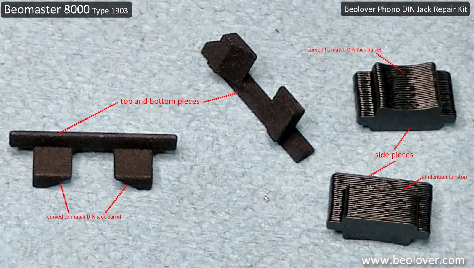
Fortunately for this type of problem Beolover makes a 3D printed repair kit.


I had used the 3D printed parts for the top and bottom edges of the phono DIN jack on the Beomaster 8000 from Texas.  That DIN jack had intact side clips though so the top and bottom Beolover parts were all that were needed on that project.

This Beomaster 8000 phono DIN jack had its bottom tab intact but was missing the top one. In addition, both the left and right side clips were broken.

The next two pictures show the installation of the phono DIN jack left side stop piece. The original side clips were a flexible, spring like plastic tab. A replacement part that works as a spring clip isn't really an option. Beolover came up with side pieces that glue to the DIN jack housing in such a way that the DIN jack cannot be pulled out (the top and bottom replacement pieces are designed to not let the DIN jack press down into the connector box).


Note that just one side (the left side) was installed first. Since this DIN jack still had its original bottom tab I only needed one of the Beolover parts for that part of the assembly.

With the left side stop piece glued in place and the top Beolover replacement part installed I was able to push the phono DIN jack back into the source input box.

The final step was to glue in the right side stop piece.


The phono DIN jack was now securely mounted where it will no longer fall in or pull out of the source input box.

Here is the completed repair.


Now back to another round of listening tests before the packing up for shipment back to Canada.
That step cannot be skipped. Whenever working with the source input connectors it is really easy for one of the small wires to break.  I do not want to risk shipping this Beomaster back to Canada only to discover there is some problem I could have easily caught with a little more testing.