The capacitor replacement on the main board and microcomputer board is complete. The microcomputer board also got a new socket for the microcomputer IC and the solder joints were reflowed on all of the board connector pins.
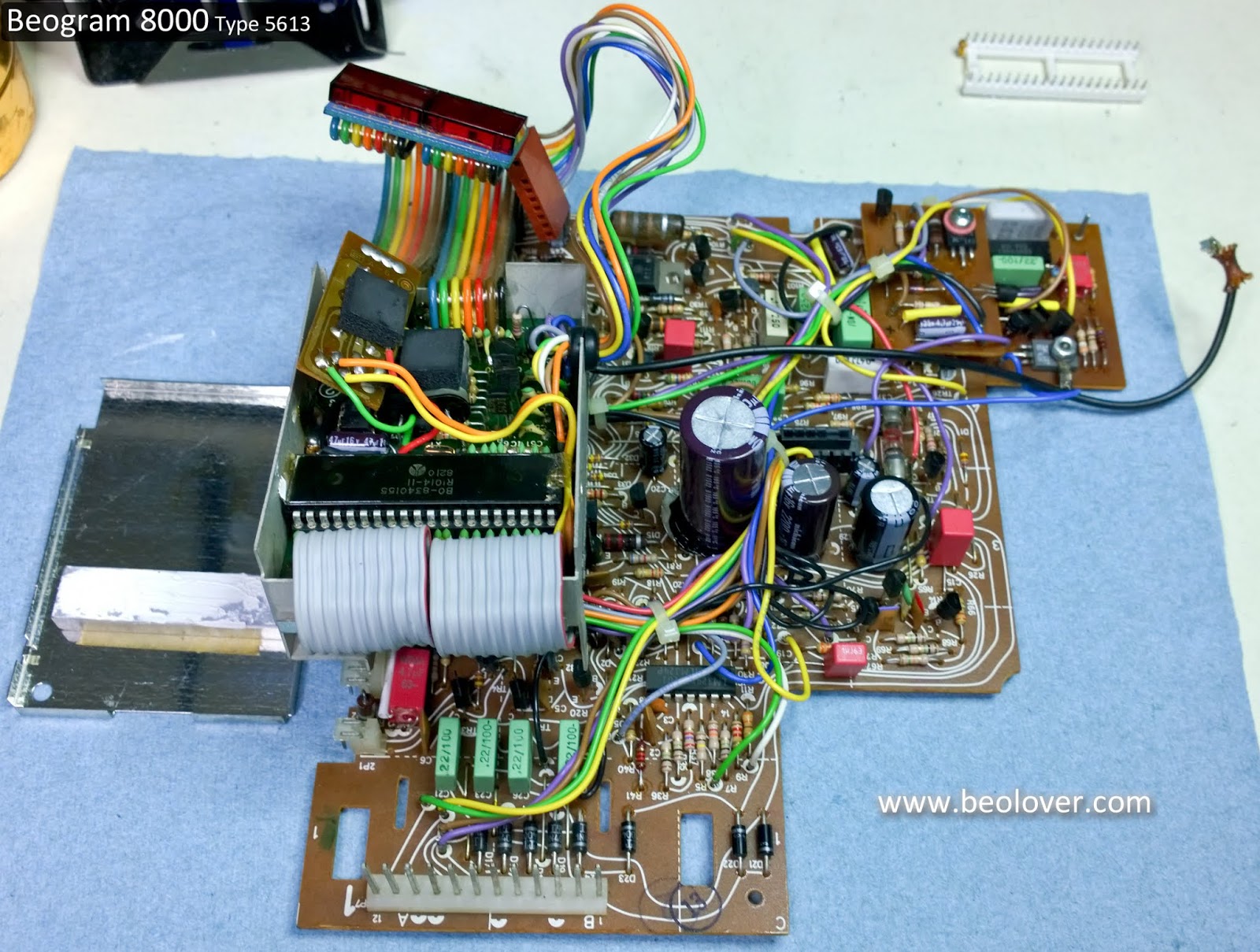
Here is the start of the main board recapping.
A nice small board plus three smaller boards. It should be pretty easy.
That's what I always think but it turns out this board takes me longer than any other Bang & Olufsen board from the period. You have to disassemble the two add on boards and the microcomputer board is difficult because there is so little space to get to the single capacitor on it.
There are two small 1uF capacitors on the trace side of the main board so I will do those first.
One got nicked but is okay.
The main board recapping goes pretty quick until I get to the largest capacitor, C27.
The original C27 is attached securely to the main board by three mounting pins which are connected to the negative side of the capacitor plus the single positive lead...four mounting points. New, replacement electrolytic capacitors don't come with the same mounting options (or at least I haven't found any) and I don't like the way the two lead replacement capacitor is wobbly using just the two mounting points.
My solution is to pop off the original C27 base (with the three prongs) and use it on the new capacitor. I solder the negative lead to the base then put a bead of black hot glue around the edge.
That makes for a good solid fit.
That takes care of the main board (and the two, small add-on boards).
On to the microcomputer board.
The microcomputer board only has one capacitor...C28. Only one but it is difficult.
Its positive lead is soldered to the trace side of the board while the negative lead is soldered to component side of the board. The proximity to the microcomputer IC makes it a little risky so to be safe I don my anti-static strap, ground the metal box containing the microcomputer board and remove the microcomputer IC.
On this particular unit the small add-on board inside the box gets its power from the C28 capacitor directly across the C28 leads. That adds to the removal difficulty.
Since I removed the microcomputer IC for safety I always go ahead and replace the 40-pin IC socket. Removing the socket also gives me more working room. The new replacement socket is a heavier duty socket.
With the microcomputer IC and socket removed I am able to get my soldering iron on C28 to remove it.
For the replacement C28 I will run both its positive lead and the positive power wire (red wire) from the add-on board together to the trace side. The C28 negative lead also goes through the PCB but does not have a solder point on the trace side.
The add-on board negative power wire (black wire, ground) solders to the C28 negative lead and the ground solder pad on the component side. You can see how having the microcomputer IC and socket make that a much easier task.
Now the new microcomputer socket can be installed.
Here is the completed microcomputer board along with the main board. I won't attach the lid to the microcomputer board box until I make sure the Beogram powers on and works.
Once I verify the recapped boards are good I will be able to start in on the service manual checks.
Featured Post
Beolover SyncDrive: DC Platter Motor Replacement for Beogram 4002 and 4004 (Type 551x and 552x)
Late Beogram 4002 and the 4004 (Types 551x and 552x), which have DC platter motors instead of the earlier synchronous AC motors usually suff...
Sunday, January 6, 2019
Saturday, January 5, 2019
Beogram 4004 (5526): Replacement of the Transport Lock Bushings
I continued working on the Beogram 4004 from Pennsylvania with the 1985 platter motor implant. While struggling to get the motor to run properly, I replaced the transport locks while I had the PCB out. This Beogram had the orange type bushings installed in the transport locks, and they are usually brittle and often come apart during shipping. Telltale signs are orange-brown splinters distributed around the enclosure, like here next to the transport lock on the right side of the enclosure:
In DC motor Beograms the replacement process is fairly painless, since the floating chassis can easily be removed as there are no soldered wires connected to it. All that is needed is to take the main PCB out, unplug the remaining plugs, and remove the transport lock assemblies. This shows the above assembly without the top plate of the lock:
After removing the other two locks, the chassis came out:
At that point I vacuumed the enclosure, since the splinters of the lock bushings have a tendency to block the floating chassis from floating since they like to accumulate in the space between the chassis and the enclosure.
Then I removed the bushings from the chassis:
and inserted the new 3D printed bushings:
They are printed as two-part assemblies that they can be inserted easily (like all featured Beolover parts, these bushings are available. Just send an email or use the contact form on the right if you need some). I installed them into all three locks: First one half is inserted from the bottom
and then the other from the top:
Then it was time to put the chassis back in:
and bolt the locks back together:
This Beogram can be shipped again!
Labels:
1562TRBG4004,
3D printed,
adjustment,
bang,
Beogram 4002,
bushing,
cabinet,
guiding,
hifi,
lock,
olufsen,
repair,
restoration,
transport,
washer
Beogram 8000 Type 5613: Finishing the floating chassis components, transformer C1 replacement & cleaning the control panel
Last night I wrapped up the work on the floating chassis components.
The cleaned tangential drive components (spindle, spindle nut, rails and new bracket) were reassembled and fitted to the floating chassis.
The spindle was lubricated per the service manual. The specified lubricants are pretty similar to the Beogram 400x. That makes sense as both series of turntables have similar tangential drive mechanics.
One interesting thing on the Beogram 8000 lubrication chart I hadn't really noticed before was the entry for the lid damping grease. It calls out a product called Kilopoise. I discovered it is made by Rocol (Rocol Kilopoise 0868). I found one seller on Ebay that sells it in small samples. Most sellers offer it in a large quantity which costs quite a lot. On these 80's series of Bang & Olufsen components that used various damping controls I have been using Nyogel 767A. It isn't cheap either. So it will be interesting to compare the Nyogel to the Kilopoise.
Here is the lubrication chart from the service manual with some notations I added.
For the spindle components I have the Molykote DX, white paste and I have a very close Rocol grease (MTS 2000 instead of MTS 1000). I also have the Esso NUTO H32. Another interesting thing about this chart compared to the Beogram 400x is this chart doesn't mention coating the rails with a thin layer of the Molykote. I have found that to still be necessary on the Beogram 800x units I have restored.
Here is the tangential arm carriage as I reassembled it.
The spindle has a thin coating of the MTS 2000 and NUTO H32 mixture. The spindle bearing and rails have the Molykote DX grease.
I should also mention that there are other modern lubricants that are suitable for this and I have used other types before. My reason for finding and using the original specified lubricant products is solely out of curiosity.
The floating chassis is ready for use.
Before getting to the task of restoring the main board and the microcomputer board I decided to knock out a couple of smaller tasks.
First the replacement of the C1 capacitor for the platter drive that is located in the transformer box.
Beolover makes a nice replacement for it that fits better than the original capacitor did.
Here is the original one.
Here is the replacement. If only all of the restoration tasks were this easy.
The next item on the list is to check out the Beogram 8000 control panel. It typically needs some cleaning and I like to add a permanently wired test connector for adjusting the forward/reverse scanning LDRs.
When I looked at the back of the control panel to open it up it didn't look too bad...but once I removed the button board I found a lot of dirt. The backside of the button board often has dust but this is a little excessive for a Beogram 800x.

The top plate and the plastic buttons were cleaned up with soapy, warm water. The rest had to be wiped with a mild cleaner and some Kimtech wipes.
Once the button board was cleaned I attached the LDR test connector. The reason I have been installing these is because I kept having cases where the LDR adjustments needed to be repeated after the Beogram 800x turntables were reassembled. It is really difficult to attach measurement probes and do the adjustment when just the control panel is lifted. There isn't much room to do what is needed. The test connector allows me to easily attach a multimeter and still have access to the adjustment screws for the LDRs.
The colors of the wires I use match the color of those corresponding signals in the ribbon cable connecting the button board to the main board. That is the Beogram 800x units that have a color coded ribbon cable. Some units, including this one, have an all gray colored cable. Nevertheless I make the test connector the same on each Beogram. The adjustment procedure calls for measurements between each LDR signal and the ground wire.
Here is the reworked control panel ready for use.
Next up will be the main board and microcomputer board restoration work.
Friday, January 4, 2019
Beogram 8000 Type 5613: Working the floating chassis components
Since I partially took apart the tangential arm assembly to check the status of the spindle nut I decided to begin work there.
I figured on cleaning the tangential arm drive parts (spindle, spindle nut, connecting bracket and rails) then lubricating them. However, I discovered a small crack in the bracket that connects the tangential arm assembly to the spindle nut.
That is too small an area to try a repair and I know I have a spare bracket in my Beogram 800x parts bin. I went ahead and cleaned the parts. Notice the rubber ends to the rear rail. I treated the rubber parts with a rubber rejuvenator product. They were looked like they were starting to dry out. The countries that have 60Hz line voltage have those type of rails and the rubber nipples were added to eliminate vibration.
I will return to the arm drive reassembly later when I retrieve the spare bracket.
Continuing...I removed the platter hub to clean underneath and lubricate it. No surprises or problems there. The metal tacho disk looks great.
Next were the replacement of the two electrolytic capacitors (0C1 & 0C2). The mica insulator under 0IC1 (+5V regulator) was shifted so I repositioned it.
I have been replacing the muting relay on the Beogram 800x turntable restorations lately because several units had faulty relays. A goal of the restoration is to make the Beogram fully functional and reliable for another forty years so it is worth replacing the muting relay while the Beogram is open. I was a little surprised to see this Beogram 8000 has the Omron type relay. I have only seen the National type relay in these turntables. The Omron relays have always been in the Beogram 8002 turntables. That works out great as I have the Omron replacements in stock.
Wednesday, January 2, 2019
Beogram 8000 Type 5613: First project of 2019
The first project of 2019 for me is a nice Beogram 8000 (Type 5613).
The turntable came well packed so I unpacked it to prepare for the assessment and work.
Let's dive right in and assess what I've got.
So far so good. Everything looks nice and original. The usual deterioration of the original double-sided tape Bang & Olufsen used has left the deck panel and compartment doors loose. Those will need to be cleaned up and re-attached.
Here are all of the components broken out. Again, everything looks good so far.
I detached the tonearm assembly so I could take a look at the tangential arm spindle drive nut. Quite a few of the last Beogram 8000 units I have come across have had spindle nuts that are partially broken.
Beolover does make a 3D replacement part for the spindle nut but this one is intact. All that is needed here is for me to clean off the old oil and grease then apply a new coat.
This Beogram 8000 already has a metal tacho disk so no need for any update there.
The floating chassis deck will just need cleaning and the two electrolytic capacitors changed.
I will also replace the original phono muting relay (not pictured) with a new, sealed type relay.
The transformer will get a new Beolover capacitor assembly for the platter motor.
The circuit boards will be recapped, solder joints on the connectors refreshed and a new IC socket for the microcomputer IC (inside the metal box).
The owner also sent his MMC-20CL cartridge to try out. I safely stored it away until this Beogram is ready.
I am already anxious to start playing records on this new turntable.
Subscribe to:
Posts (Atom)