Featured Post

Beolover SyncDrive: DC Platter Motor Replacement for Beogram 4002 and 4004 (Type 551x and 552x)

Late Beogram 4002 and the 4004 (Types 551x and 552x), which have DC platter motors instead of the earlier synchronous AC motors usually suff...

Wednesday, November 25, 2020

Beogram 4000: A Fun Evening with a Smoking Solenoid Resistor

This is another installment of my 'A Fun Evening with...' series...;-). A Beogram 4000 that I restored this summer came back with a non-working arm lowering mechanism and the emission of a 'burnt smell'.

Oh well...I extracted it from the box and put it on the bench and removed the aluminum plates for a closer look.

After I plugged in and pressed ON, the unit started normally, but at the LP set-down point the arm would not lower. Instead the unit gave me a vivid demonstration of 'burnt smell', while a thin plume of smoke rapidly developed on the left side of the PCB that carries the carriage switches.

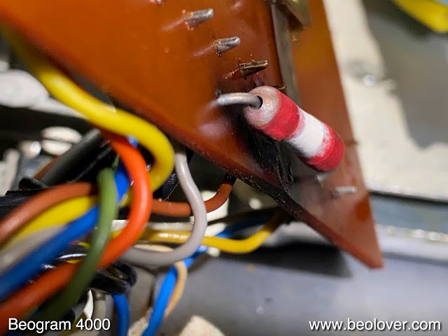
I quickly pulled the plug and lifted the PCB and found a browned solenoid resistor (7R1) and a blackened board:

I immediately thought the culprit might be the solenoid power transistor (0TR4) that regulates the current through the coil:

This TIP41 is usually a pretty resilient device, but in the case of the solenoid it also sees some pretty significant currents. I extracted it and put it into my transistor tester. And it tested seemingly o.k.:
This threw me a bit off the right track. First, I thought maybe the resistor itself had an issue (unlikely since it is wire wound, and it measured at 9 Ohm), then I suspected the solenoid (but it had its prescribed ~9.5 Ohm, i.e. seemed o.k.). 
I plugged the unit in for another measurement, and now the solenoid immediately activated after I plugged it in. Something had gotten worse. Since the solenoid is directly connected after the rectifier of the 24V rail this now really suggested that the transistor now was a permanent short circuit. 

So I replaced the transistor with a new TIP41C: 
Then I measured the original one again, and now it came up as a voltage divider, supporting my hypothesis:
Another good example to not blindly trust a transistor tester. They test at low currents and this can mean that results are displayed that have nothing to do with the actual situation the device is seeing in its circuit.

After bolting the TIP41C to the enclosure bottom, I plugged the unit in, and the solenoid did not activate anymore. Encouraged, I pressed ON and now everything worked as it should. The carriage went to the LP set-down point and the arm lowered. At that point I decided that I better also replace the solenoid resistor

and the two transistors that drive the TIP, 1TR10 and 1TR11:
I replaced the TR11 with a NTE128 and TR10 with a new BC547B:
The reason to replace these two was that in an earlier 4000 restoration TR10 was out of spec with a too low gain, and I increasingly think that transistors where the gain is critical or that carry a high current may need to be replaced during a full restoration of a Beogram 4000. Life is a learning curve! This is Beolove!


Monday, November 23, 2020

Beogram 4002 DC Platter Motor Restoration

I recently received the DC platter motor from a Beogram 4002 located in Iowa. This shows the motor as received:

I took the motor apart to get to the bearings:
They are the two small donuts on the black pad. I immersed them in motor oil and pulled a vacuum. Immediately strong bubbling started:
This indicates that air is being drawn from the empty pores of the bearing material, making room for the inter-diffusion of oil. When all the pores are full with oil the bubbling stops. In this case it took about 72 hrs until the process was complete. This shows the bearings after extracting them from the oil:
I put the motor back together and installed it in one of my Beogram 4002s for a 24 hrs test run with my 
BeoloverRPM device, which allows logging the RPM in 10s intervals over extended periods of time:
This is the curve I measured after about 24 hrs:
This is pretty much as good as it gets with the Beogram DC motors. This motor is ready for duty again!


Saturday, November 21, 2020

Beogram 8002 Type 5633: Restoration and Test Drive with George Benson

I just completed the restoration of the Beogram 8002 (5633) that I recently received from Michigan. My initial assessment of the unit is discussed here. This post gives a summary of the work done. The first step was to open up the unit (disconnect the three leaf springs from the chassis, remove the two screws on the left side of the enclosure, then flip open to the right):

I extracted all vital parts and put them on the bench:
This shows the PCB in its original condition:
I replaced all electrolytic capacitors with new Japanese 105C types:
There is one more capacitor in the microcontroller 'can':
The motor phase capacitor is in the power block. I found that someone already had replaced them with two back-to-back unipolar types:
Since they were flopping around a bit dangerously, I replaced them with my more orderly 3D printed assembly:
The two remaining capacitors to replace were the 5V voltage regulator in- and output capacitors:
This shows the new ones in place:
The next step was to add a switch that allows connecting system and signal grounds. This is useful if there is a hum when connecting the unit to a RCA input:
Then I focused on the mechanical aspects. Usually, the carriage transport mechanism is gunked up with old lubricants. I extracted the parts and cleaned them in an ultrasonic cleaner:
I put the newly shiny looking parts back in with small dabs of synthetic grease on critical points:
Then I adjusted the carriage transport control voltages to ~620mV according to specifications for both directions:
Before I could put the innards back into the enclosure I needed to glue the main aluminum plate back into place. They often come off due to disintegrating double sided tape. A good way to remove the old tape is by soaking it with isopropyl alcohol over night. In the morning I was able to remove it with a plastic scraper:
The unit also had lost its hood bumpers:
I drilled the old remains out and installed snippets of an O-ring, which I cut to 1 mm length
And then I put everything back together, and it was finally time for a test drive! I selected "Space" by George Benson, which I recently acquired. Another great album from the CTI label. George Benson recorded it in 1978 (CTI 7085). This vintage album was cleaned ultrasonically with a CleanerVinyl ProXL setup. After the clean it sounded like new! This shows the Beogram 8002 in action:
Beautiful! I will now play it a bit longer, and if nothing else comes up it will soon be time to return it to its owner in Michigan.


Thursday, November 19, 2020

Beogram 4002 Type 5513 - DC Motor, Main PCB and RPM Panel Restoration

I recently received the DC motor, the main PCB and the RPM panel from a Beogram 4002 (5513) in Arizona for restoration. The unit exhibited the usual RPM fluctuations. I opened up the motor first since it tcan take up to three days to infuse dry bearings with oil. This shows the motor as received:

I took it apart to get to the bearings:
The bearings are the two small donuts on the black pad. I immersed them in motor oil and pulled a vacuum. Immediately vigorous bubbling started, indicative of air being drawn from the porous bearing material. This makes room for oil to interdiffuse into the bearing.
After about three days the bubbling stopped and I extracted the bearings from the oil:
I put the motor back together and set it aside. The next step was rebuilding the main PCB. This shows the original condition:
This is a detail shot of the 'RPM section' with the 33/45 relay and the trimmers for adjusting the speed:
This are the replacement parts: A modern encapsulated relay with an adapter board that has the footprint of the original Siemens relay, and two multi-turn trimmers to replace the often oxidized single turn original RPM trimmers
This shows the parts installed:
I also replaced TR3 that amplifies the record sensor signal. It often goes out of spec with the consequence that the deck cannot distinguish anymore between no record on the platter and the presence of a record. This can get dangerous for the stylus. This shows the original BC183C transistor with fixed 1M Ohm biasing resistor in place:

And after replacement with modern 2N5089 high gain type and a multi-turn trimmer enabling exact biasing of the transistor to obtain the specified 4 V at the collector:
I also replaced all the electrolytic capacitors since they often go out of spec at this point in time:
The next step was to restore the RPM panel. It came with some strange 'custom wiring' (oh, that human ingenuity!!..;-):
I decided to replace this mess with a complete trimmer unit from a scratched up panel that I had on the shelf. I removed the unit from the rewired panel, which revealed a completely wavy white background label. This is what happens when the original light bulbs are replaced with modern bulbs that have a higher output power. This makes them run hotter, and that damages the label.
Anyway, I put the replacement in place and installed my LED replacement boards. This is a good idea since LEDs run much cooler than bulbs, and that keeps the RPM trimmers in this panel from changing their temperature, which sometimes can also result in RPM fluctuations while playing a record:
After installing the LED panels I put the original covers back on. Since the LEDs do not cover the small slots in the covers (for the bulb holders), I put a bit of black tape over them to prevent light from seeping out. This can sometimes be seen though the crack between RPM panel and small aluminum plate of the Beogram.
Then it was time to test the setup. This shows the RPM panel in action: The nice incandescent looking color (while correctly showing the indicator in red) is a consequence of using red-green LEDs tuned to yield a warm incandescent glow:
The next step was adjusting the bias of TR3 to get 4V at the collector:
Then I measured the sensor response with the oscilloscope:
This signal looks good, and the deck correctly recognized 7" and 12" records, and also their absence. The final step was testing the RPM stability of the entire setup. For this I installed my BeoloverRPM device and measured the RPM in 10sec intervals for about 24 hrs:
This is the curve I measured:

This is an excellent result. It is probably one of the best DC motors that I encountered since I started Beoloving. This setup is ready for duty again. Time to send it back to Arizona!