Featured Post

Beogram Commander Remote Control: Maybe This is the Final Version!..;-)

This is a follow up to my recent post about the redesigned Beogram Commander remote control board, which now works in both (DC-motor) Beogr...

Thursday, June 28, 2018

Beogram 4002 (5513): Keypad and RPM Panel

I noticed that some of the Beogram's control panel buttons were slow to respond when pressing them. That usually means oxidation on the keypad contacts so I opened up the keypad assembly.
Sure enough, you can see the dull key contacts.


I unsoldered the contact pads and removed them for inspection. They didn't look too bad but the leaf contacts that the actuators press down on are all oxidized.


I used a fiberglass brush and some Deoxit to protect from future oxidation. The contacts all look nice and shiny again.


The last part of the electrical work is to change out the lamps for the RPM indicators. We recommend this because during the platter motor stability testing the LED replacement modules resulted in further stability of the motor speed. The RPM indicator lamps are part of the circuit that controls the platter motor. Each speed indicator has a knob to adjust the pitch (speed).

Here is the RPM indicator module with the original incandescent lamps.


Here is the RPM indicator with the Beolover lamp replacement modules.


The Beolover lamp replacement module is designed to work with the pitch control circuit and the SMD LED components used have been adjusted to mix light colors to match the original incandescent lamps.

Here are the 33 and 45 RPM speeds with the new light modules. The control panel buttons operate immediately as they are pressed now.


All of the Beogram functions are operating now. The next step is to check and adjust the Beogram per the service manual. Once those adjustments are made and all the checks pass it will be time to play vinyl again.

Wednesday, June 27, 2018

Beogram 4002 (5513): Electrical Work and Initial Tracking Adjustment

On to the electronic board restoration tasks. There is the main control board to recap and change the RPM relay (plus RPM trimmers) on. Then there is the output board with its phono muting circuit. It should be noted that the muting relay is the only electrical component other than wiring that is involved with the phono audio signal. Most of the electronics in the turntable are for controlling the platter motor, tangential arm, indicator lamps and operator controls. Those circuits are not in the audio path.

Here is the main control board before the recap. It has a few electrolytic capacitors and quite a few tantalum capacitors. I will change the capacitors that are 4.7uF and above with new 105°C, Nichicon capacitors. On the values smaller than 4.7uF I will use WIMA MKS polyester capacitors. When there is room I usually replace the 4.7uF capacitors with WIMA MKS as well but they are too large for this application. Another thing to note is that I will change the 1C10 electrolytic capacitor from its original 0.47uF value to 10uF per Beolover's test results of the restored platter motor. That value was determined to give the best speed stability with this particular motor.


Here is the restored main board.


Now the output board before


...and after. Note that I installed our usual grounding switch so signal ground and chassis ground can be engaged or disengaged depending on the owner's needs.


I am now ready to see how this Beogram acts with its mechanical components cleaned/lubricated and the electrical components updated. For the first electrical power on test I removed the tangential arm motor belt and left the platter off. That way if something is not right I don't have to worry about a moving component going somewhere. I also removed the arm position scale from the tangential arm transport to take a look at the switches and the position sensor lamp.


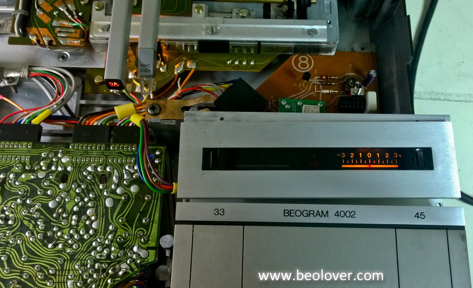
With the Beogram plugged the main reservoir capacitor shows that it is at just over 30 VDC which is good. The fixed arm sensor lamp is illuminated and so is the 33 RPM speed indicator lamp. The platter motor and tangential arm motors are turning. That is expected since the position scale is off and there is nothing there to turn the SO switch off.

However, there is one fault I can see right away and that is the tangential arm position sensor lamp is not lit.


Without the arm position sensor lamp the control logic cannot determine where the tangential arm assembly really is.

I replaced that with an amber T-1, round LED.


The replacement LED I use has a wavelength of 591nm and luminous intensity value of 13000 mcd. The viewing angle is 15°.  The important thing here is that the sensor detects the light and is able to supply the control circuit with the proper voltage level. I will do a more detailed check of that sensor voltage later when I go through the service manual adjustment/checks.

Here is the new position sensor lamp installed and working.


This is a good time to prepare the initial setting for the tangential drive tracking sensor. I had to disassemble most of the tracking sensor components when cleaning up the oil so there is a good chance that the tracking alignment is off now. I visually set the tracking sensor aperture to be centered but that was just a guess.


Using the aperture position adjustment screw I set the aperture in a position where the arm pivots easily and, when the arm is lowered, the tangential arm drive motor doesn't try to drive it somewhere.
Then I play with the tracking sensitivity adjustment screw and the aperture position to find a place where the sensitivity screw can affect the arm moving forward (when it is lowered). The goal here is to set the arm tracking control where I have enough play in the tracking sensitivity screw to lock in the tracking later (during the service manual adjustments). With that set up I can tighten down the aperture position screw.

Now on to replace the speed indicator lamps from the original incandescent lamps to Beolover's replacement LED boards. Those are the final piece of obtaining optimum platter speed stability.

Monday, June 25, 2018

Beogram 4002 (5513): Floating Suspension, Reservoir Capacitor & Platter Motor

This project is heading into the home stretch now. In this post I am showing the remounting of the floating chassis in the cabinet along with changing out the reservoir capacitor and installing the rebuilt platter motor.

Here are the components for mounting the floating suspension back in the cabinet.


The longer end of the threaded pin goes on the bottom. It is important to attach the wing-nut so that it is right at the start of the thread. I attach mine so there is enough thread in place to hold the nut and the outer part of the nut is flush with the top most thread. The idea here is to provide maximum space for the floating chassis when the the lock is disengaged. Turning the threaded pin will move the two lock nuts closer together (locking the suspension) or further apart (unlocking the suspension).


Because most of the Beogram 400x turntables have deteriorated transport lock bushings Beolover created replacements using 3D printing technology. Here are a set of the Beolover transport lock bushings for the three Beogram suspension mounts. There are a total of six 3D printed parts.


Now the rest of the suspension mount pieces can be attached. Just like the first wing-nut I started out with the top of the nut flush with the first thread.


The next re-installation in the cabinet is the reservoir capacitor.  The original reservoir capacitor is actually two in one. Not all Beogram 400x turntables have this same type of reservoir capacitor so make sure you check carefully and identify what your 400x type has.


I removed the wires and installed the Beolover replacement capacitor assembly.


It looks great. Now to install the platter motor that Beolover rebuilt for this project.


One more look over the reassembly so far shows everything looking good.


The next step is to work on the main board and the output board.

Thursday, June 21, 2018

Beogram 4002 (5513): Tangential Arm Assembly Oil Cleanup and Restoration

This second Beogram 4002 project from Houston left off with cleaning up debris and oil from the inside of the cabinet. I continued the oil cleanup after removing the tangential arm assembly from the floating chassis.

Oil was found everywhere. From the lowest level of the arm mechanics to inbetween switch contacts.
Here is the tangential arm position sensor assembly completely stripped down for oil cleanup.


Once everything was wiped down and as much of the old oil removed I could begin going through the arm assembly restoration and adjustment steps.

I am doing something a little different on this Beogram regarding the lubrication. Up until now I have always used modern available lubricants like silicone grease and synthetic oils when going through a Beogram 4002 turntable project. I spent the last few weeks searching for the lubricant products that are listed in the Beogram 4002 service manuals. I say manuals because B&O changed a few of the lubricant instructions in the various Beogram 400x manuals.

I will start with the tonearm damper. After taking it apart and cleaning the damper assembly I reassembled it using Dow DC 200 fluid for the damper lubricant.


Next was the tonearm assembly spindle and tie-bar shaft reassembly. For the lubrication of those the service manual calls for the following -
On the spindle: Rocol MTS 1000 diluted to an oily viscosity using Esso NUTO H44 or H32.
On the tie-bar shaft number 137: Molykote DX paste (white)

I was able to find some Rocol MTS 2000 and Mobile NUTO H32 for the spindle lubrication. They were not the easiest products to acquire.


The Molykote DX white paste however is easily available. Here is the tangential arm assembly reinstalled on the floating chassis.


At this point of the mechanical restoration I adjust the tonearm lowering damper, tonearm to fixed arm parallelism and calibrate the tonearm counter weight for the tracking force.


This tangential arm assembly and floating chassis are ready to be reinstalled in the Beogram cabinet.

My next step is to prepare the cabinet by installing new Beolover transport bushings (3D printed parts) and install the Beolover replacement reservoir capacitor assembly (another 3D printed part).

After that it will be time for the remainder of the electrical restoration work - capacitor replacements, relay replacements and the Beolover rebuilt platter motor.

Sunday, June 17, 2018

Beogram 4002 DC Motor Restoration: Oil Infusion of Bearings and New Spark Snubbers

A DC-motor from a Beogram 4002 recently arrived from Austria for restoration. This shows the motor:
Most of these motors need their dry Oilite bearings re-infused with fresh oil under vacuum. For this to happen the motor needs to be completely disassembled:
Then I submerged the bearings in motor oil and pulled a vacuum:
Immediately vigorous bubbling emerged from the bearings, indicating that air was leaving the pores of the Oilite material to make room for fresh oil. After about 48 hrs the bubbling stopped and I extracted the bearings from the oil:
I reassembled the motor and implanted it into one of my Beogram 4002s for a 24 hrs RPM test with the BeoloverRPM device:
The BeoloverRPM can log the RPM of a Beogram over extended periods of time in 10s intervals. The blue curve in the graph below is what this first measurement yielded:
As you can see there were a few RPM drops during that 24 hrs measurement period. If such drops still occur after infusing the bearings with oil, it usually points to unstable spark snubber devices on the rotor of the motor. I took the motor out and extracted the rotor for spark snubber replacement.
This shows the rotor in its original condition:
The snubbers are the three yellowish devices arranged in a circular pattern around the commutator.
I removed the original snubbers to make room for modern TVS diodes, which work well as replacements. This shows the original 'ring' of snubbers together with the replacements prepared for soldering (the contact tabs of their SMD packages need to be bent outwards that they can be soldered to the rotor terminals
This shows the TVS diodes installed on the rotor.
If you try this at home, please, note that the TVS diodes need to be pressed a bit into the windings of the rotor while soldering them in that they are far enough away from the commutator and the brushes. Otherwise they can interfere with the brushes when the motor runs. I put the motor back together and installed it again in the 4002. Another 24 hrs of RPM logging and the red curve in the graph above was obtained. It seems the spark snubber replacement cured the RPM breakdowns. This motor is ready to play some nice vinyl again!