Featured Post

Beogram Commander Remote Control: Maybe This is the Final Version!..;-)

This is a follow up to my recent post about the redesigned Beogram Commander remote control board, which now works in both (DC-motor) Beogr...

Monday, December 31, 2018

Beogram 4004 Type 5526: Second Beogram 4004 from Texas service manual checks to playing records

I reached the home stretch of this Beogram 4004 turntable. It was almost as pristine as the first one but did require a few adjustments per the service manual.

Running through the service manual checks I started with checking the sensor signals from the carriage position sensor and from the fixed arm. Because the LED lamp was changed for the carriage position sensor I needed to make sure the voltage on the sensor, 4IC1, is 5V when the sensor is on a clear part of the moving position scale.


That sensor and new LED lamp are now adjusted where they should be.

For the new Beolover lamp assembly in the fixed arm for the record detection the voltage on the collector side of 1TR3 should be a steady 4V when a record is present or the platter is off.


That measurement was initially low so I had to raise the collector voltage using the new 2MΩ multi-turn trimmer I installed in place of the original, fixed 1MΩ resistor 1R26.  The reason for that is described in this Beolover post.

Now that the voltage level at the collector of 1TR3 is set I checked what the actual pulse signal looked like when the platter is installed and turning.


A nice healthy detector arm signal from an empty platter. I think it is safe to press the fixed arm's sensor assembly back into the arm.


On to the platter to tonearm mechanical height adjustment. The platter was a little low on this Beogram. It should be 23mm from the deck of the platter to the top of the fixed arm.


The platter height (and levelling) is done with the platter main bearing assembly. The large nut is loosened so the threaded bearing can be rotated up or down as needed for the adjustment.


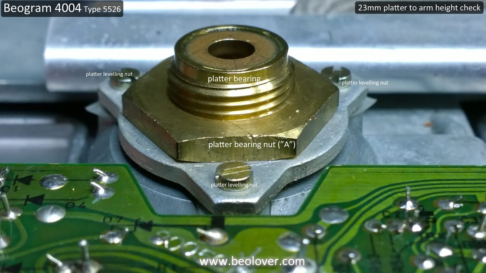
In this case I needed the platter to be lowered a little bit.

I check the height at the edge of the platter and at the center.


That is right on the money.

During the platter height check I determined that the platter needed a little levelling so I adjusted those screws as well.

The next mechanical type check is for the arm lowering limit. For this check the stylus should be about 0.5mm above the low rib of the platter. That provides a little bit of cushion should the arm try to drive towards the center of the platter without a record. The stylus hitting the high rib of a rotating platter could easily shear off the stylus.


The stylus/tonearm distance check is done with a string from the center spindle of the platter to the edge of the turntable. I can use the string to make sure the travel of the stylus remains on the center line.


The cartridge tracking force check showed it needed some recalibration so I adjusted the tracking force gear position to bring it into line. I calibrate it for 1 gram.


This Beogram 4004 restoration installed a new tangential tracking sensor lamp assembly (a Beolover custom part) so I figured I would have to go through that whole adjustment procedure and I did.

The platter belt is removed and the adjustment calls for manually rotating a test record with the platter engaged and observing when the tangential drive motor advances the arm assembly. On initial lowering of the tonearm on a record the platter should go through two rotations before the arm assembly is advanced. After that it should advance on every rotation.


The following pictures show the adjustment screws.


It always takes a few iterations but eventually it was set per the service manual.

I attached the platter belt again and performed the platter motor speed adjustments.


It is very nice to have the Beolover RPM measurement tool and both speeds adjusted easily with the new multi-turn trimmers I installed on the controller board.

The final adjustment steps were strictly cosmetic, mechanical adjustments. I made sure the cabinet deck and platter were level and the floating suspension worked.


The Beogram 4004 turntables still look amazing!

The first real record play was next and I fully expected it to play great as all of the tests passed. No problems. I moved the Beogram to my office and put on an MMC-20CL cartridge followed by some seventies big band music.


The dust cover on this Beogram 4004 could use a little polishing so I will have to do that as the last step...but first I am going to reward myself with a nice, long listening break.

Saturday, December 29, 2018

Beogram 4004 Type 5526: Second Beogram 4004 from Texas almost ready for record play

In this update I have the second Beogram 4004 from Texas reassembled and nearing the point of playing records again.

I completed the last few component restoration tasks.

First there was the RPM indicator panel update to the Beolover RPM indicator modules. Those are custom plug 'n play LED lamps for the RPM panel. Platter motor stability tests with the LED RPM lamps show improved motor speed stability so when we restore a Beogram 400x with a rebuilt platter motor we always replace the RPM indicator lamps and the RPM relay on the controller board.


Here are the Beolover RPM indicator modules installed.


The keypad button contacts usually have oxidation that needs cleaning up.


The contacts on this one aren't too bad but while I have the keypad opened up I cleaned it with a fiberglass brush and Deoxit.


Now the components can be reassembled in the Beogram cabinet.

For the floating chassis I installed the Beolover 3D printed transport lock bushings.


With the bushings in place I prepared the transport lockdown screw assemblies. I will just show one as the other two are the same.


The upper and lower locking nuts were installed at the very ends of the threads to give maximum distance between them when the floating chassis is unlocked.

Next was the installation of the new reservoir capacitor. The new capacitor uses a Beolover 3D printed housing so it fits perfect in the cabinet.


Looks great.

Now for the reinstallation of the DC platter motor that Beolover restored for me at the beginning of December.


Now for the installation of the controller board, output board, keypad and RPM indicator panel.

This Beogram is ready to try a power on test.


Lights are on, the motors turn...those are good signs.

The next step is to measure the voltages and key sensor signals before starting the service manual checks.

Friday, December 28, 2018

Beogram 4004 Type 5526: Working the floating chassis components on the second Beogram 4004 from Texas

I find it easiest to work on the tangential arm assembly and other components that live on the Beogram floating chassis when everything is removed from the cabinet.


Earlier I spotted a couple of problems with the tangential drive motor position in its housing. I also noticed the usual hairline cracks in the drive pulley. So my first step was to remove those two components.


The vibration dampening material hasn't completed deteriorated in this Beogram but it has started. With most of it still intact this one won't be such a mess to clean up after.

In the first Texas Beogram 4004 project it was decided to leave the original tracking sensor in place. On this second Beogram 4004 restoration the owner wanted to go with the Beolover replacement tracking sensor lamp module. It isn't difficult to install and is even easier when the tangential drive motor and pulley are removed.


The first Beogram 4004 unit had a burned out carriage position sensor lamp. From the symptoms the owner described on this unit I suspected this one was out too. I removed the original LED lamp and tested it. Sure enough, it was dead.


Another difference in this second Beogram 4004 restoration is the fixed arm (platter) detector lamp will be replaced with the Beolover replacement part. I have done a few of these and while not extremely difficult the task requires patience, care and a steady soldering hand.

The fixed arm sensor assembly mount pulls out from the end of the fixed arm. Do not force it or use a tool to pry the black plastic housing out of the aluminum frame. Doing so could damage the arm or leave an unsightly scar.

Here is the sensor assembly pulled out of the arm.


Here is the new sensor lamp assembly soldered in place. I will leave the sensor assembly out of the fixed arm for now until I can test it for final positioning. The design of the new part will always get it close to where it needs to be but we always measure the signal and fine tune the position for the best signal.


Next up is the arm lowering damper assembly.
This Beogram is in good shape but some of the parts involved in the arm lowering and raising don't feel like they operate as smooth as I expect.
I removed several key parts for the arm lowering to inspect, clean and lubricate them.


The arm damping cylinder is another lubrication where I found the original lubricant called out in the service manual. You can use substitutes as shown in other Beogram 400x restorations on this site but I wanted to see what the original lubricants were like and was able to acquire some.


Continuing with the tangential arm lubrication I removed the spindle assembly for cleaning and re-lubricating. The first time I removed one of these Beogram spindles I thought it was really dirty from the years of use.


It turned out that is the color of the original oil/grease mixture the factory lubricated the Beogram spindle with (Rocol MTS 1000 plus Mobil Nuto H32 oil).
I cleaned the spindle parts and re-lubricated them as I did the first Beogram 4004.

Next I rewrapped the tangential drive motor with new vibration damping material (1/16" self adhesive neoprene material).

I also installed a new drive pulley (aluminum). The drive motor and pulley look centered and aligned now.


I finished the lubrication of the tangential drive assembly and now it is ready to go back into the Beogram 4004 cabinet.