The final incandescent bulb to be replaced in the Beogram 4004 (5526) that I am currently restoring was the bulb in the sensor arm. This bulb enables the record detection circuitry and therefore is essential to the proper working of the turntable. I recently developed a flex-PCB based LED replacement assembly, which 'folds' into the small bulb compartment. This places the LED in the right spot to be projected through the lens onto the record that is being played. This shows the original bulb in place together with the LED replacement:
I removed the lightbulb:
and installed the LED assembly:
The assembly is drop-in, i.e. directly replaces the lightbulb pulling the same amount of current. This is important to not confuse the record detection circuitry. This shows the LED in action:
Since it is a 'warm white' LED, it has enough red light components to accurately illuminate the red-orange B&O logo at the end of the arm.
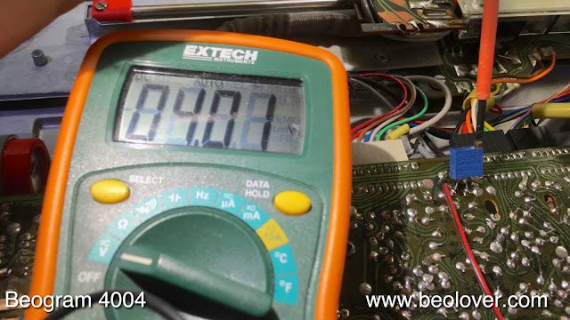
The design of the detection circuit has one flaw, that sometimes manifests itself by neutering the detection circuit allowing the arm to drop even if there is no record present. This is caused by biasing the TR3 transistor that is responsible for the initial amplification of the sensor signal too low. This can be fixed by replacing resistor R26 with a 2MOhm trimmer that can then be adjusted to yield 4V at the collector of TR3 when there is a record present (i.e. no sensor signal coming in from the black ribs passing underneath the arms). A more detailed description of the circuit and its improvement can be found here).
Once R26 has been removed it is a good idea to install the trimmer temporarily on top of the circuit board, so it can be adjusted while the board is in place:
After adjusting the trimmer to yield 4V at the collector of TR3, it can be installed 'below deck':
It fits neatly between the other components around TR3, as if the designers of the boards foresaw that the Beolover would come up with this fix in 2017!..;-).
After this upgrade it was time to measure the sensor response at the collector of TR3. This shows the signal trace while the platter was spinning under the sensor:
Each dip corresponds to a black rib passing under the sensor. The amplitude of the signal should be close to 6V to make the sensor work properly. Generally it can be said that if the dips are not going all the way to zero, the position or brightness of the light source (LED) is not good enough, and if the amplitude is not reaching 6V on the upper end, the collector voltage at TR3 is too low and needs to be adjusted.


No comments:
Post a Comment
Comments and suggestions are welcome!