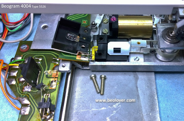
I find it easiest to work on the tangential arm assembly and other components that live on the Beogram floating chassis when everything is removed from the cabinet.
Earlier I spotted a couple of problems with the tangential drive motor position in its housing. I also noticed the usual hairline cracks in the drive pulley. So my first step was to remove those two components.
The vibration dampening material hasn't completed deteriorated in this Beogram but it has started. With most of it still intact this one won't be such a mess to clean up after.
In the first Texas Beogram 4004 project it was decided to leave the original tracking sensor in place. On this second Beogram 4004 restoration the owner wanted to go with the Beolover replacement tracking sensor lamp module. It isn't difficult to install and is even easier when the tangential drive motor and pulley are removed.
The first Beogram 4004 unit had a burned out carriage position sensor lamp. From the symptoms the owner described on this unit I suspected this one was out too. I removed the original LED lamp and tested it. Sure enough, it was dead.
Another difference in this second Beogram 4004 restoration is the fixed arm (platter) detector lamp will be replaced with the Beolover replacement part. I have done a few of these and while not extremely difficult the task requires patience, care and a steady soldering hand.
The fixed arm sensor assembly mount pulls out from the end of the fixed arm. Do not force it or use a tool to pry the black plastic housing out of the aluminum frame. Doing so could damage the arm or leave an unsightly scar.
Here is the sensor assembly pulled out of the arm.
Here is the new sensor lamp assembly soldered in place. I will leave the sensor assembly out of the fixed arm for now until I can test it for final positioning. The design of the new part will always get it close to where it needs to be but we always measure the signal and fine tune the position for the best signal.
Next up is the arm lowering damper assembly.
This Beogram is in good shape but some of the parts involved in the arm lowering and raising don't feel like they operate as smooth as I expect.
I removed several key parts for the arm lowering to inspect, clean and lubricate them.
The arm damping cylinder is another lubrication where I found the original lubricant called out in the service manual. You can use substitutes as shown in other Beogram 400x restorations on this site but I wanted to see what the original lubricants were like and was able to acquire some.
Continuing with the tangential arm lubrication I removed the spindle assembly for cleaning and re-lubricating. The first time I removed one of these Beogram spindles I thought it was really dirty from the years of use.
It turned out that is the color of the original oil/grease mixture the factory lubricated the Beogram spindle with (Rocol MTS 1000 plus Mobil Nuto H32 oil).
I cleaned the spindle parts and re-lubricated them as I did the first Beogram 4004.
Next I rewrapped the tangential drive motor with new vibration damping material (1/16" self adhesive neoprene material).
I also installed a new drive pulley (aluminum). The drive motor and pulley look centered and aligned now.
I finished the lubrication of the tangential drive assembly and now it is ready to go back into the Beogram 4004 cabinet.
Featured Post
Beolover SyncDrive: DC Platter Motor Replacement for Beogram 4002 and 4004 (Type 551x and 552x)
Late Beogram 4002 and the 4004 (Types 551x and 552x), which have DC platter motors instead of the earlier synchronous AC motors usually suff...
Friday, December 28, 2018
Beogram 4004 Type 5526: Working the floating chassis components on the second Beogram 4004 from Texas
Subscribe to:
Post Comments (Atom)


No comments:
Post a Comment
Comments and suggestions are welcome!