Featured Post

Beolover SyncDrive: DC Platter Motor Replacement for Beogram 4002 and 4004 (Type 551x and 552x)

Late Beogram 4002 and the 4004 (Types 551x and 552x), which have DC platter motors instead of the earlier synchronous AC motors usually suff...

Thursday, June 20, 2019

Beomaster 8000 - Workbench Unit - Testing a replacement device for the AD 10/278 Multiplex Switch on the preamplifier board

One of my first projects utilizing my new, dedicated workshop Beomaster 8000 unit is to test out a replacement device I created for the BM8000 preamplifier board's input source switching ICs - IC102 and IC202. They are the no-longer-available AD 10/278 multiplexer device.

Here is the circuit diagram of the Beomaster 8000 preamplifier source select switching.


As you can see there are actually two types of analog switch devices. 3IC102 and 3IC202 are AD 10/278 devices for selecting between FM, Phono and Tape 2 left and right channel sources. 3IC4 is an AD 10/192 device that selects between Tape 1 or whichever source is selected with 3IC102 and 3IC202. Selection control of course comes from the Beomaster 8000 Microcomputer board (via 3P14).

Once in a while AD 10/192 devices can be found for sale but I have never been able to find NOS AD 10/278 ICs. Concerned that a failed AD 10/278 can bring an entire Beomaster 8000 restoration project to a grinding halt I decided to look into making a modern replacement. I was also motivated by reports from some Beomaster 8000 owners who complained about crosstalk between the FM source and Phono source. I felt that if that were to occur it would most likely be due to a problem with the 3IC102 and 3IC202 analog switch. However, I must confess, after quite a number of Beomaster 8000 restorations I have yet to experience any crosstalk problems between input sources myself. Still...another reason to create a replacement device.

To follow Beolover's lead in creating replacement parts for the various Bang & Olufsen restorations we have done, a key goal is that the new part be a direct plug and play replacement. No modifications to the Bang & Olufsen component to use it. So in the case of the AD 10/278 replacement I needed a design that would result in the old 3IC102 and/or 3IC202 desoldered for removal...and the replacement inserted and soldered into place.

I believe I have accomplished that with a custom adapter board and a modern three channel SMD multiplexer device designed for audio switching.

I started with a prototype using the replacement device in a standard DIP package layout and a breadboard circuit where I could test inputting test signals and selecting channels just like the Beomaster 8000. Once I had that perfected I sent my design off to have my adapter boards made.


Here is my breadboard tester for the AD 10/278 with the various test devices.


Confirming that the prototype and first replacement units function just like the original devices I installed the first two replacement units in a Beomaster 8000 preamplifier board.


Then the preamp board into my Beomaster workshop unit.


The results are as good as I expected. The source selection works just as it should and I cannot hear any crosstalk between selected sources.

I need to run some additional testing of course but I am thrilled with these initial results.

Monday, June 17, 2019

Beomaster 8000 - Workbench Unit

After restoring quite a few Beomaster 8000 receiver units I have developed several bench testing aids. I have some jigs for testing the rebuilding of displays and I have a test setup for testing the Beomaster 8000 output amplifier assemblies.

During various Beomaster 8000 projects I have also restored a number of Beomaster 8000 spare circuit boards. To checkout my spares and to aid in Beomaster 8000 diagnostic trouble-shooting I have been wanting to built up a dedicated, workbench unit. This would be a test unit I could swap boards in and out of easily for testing purposes. I had a couple of spare Beomaster 8000 chassis laying around so the time finally arrived to implement this workbench Beomaster 8000 unit.

Here is the completed workbench Beomaster 8000. It will remain in its service position and never be completely reassembled. I want it always available for testing.


Even the startup circuit is left open for measurements and to test the startup relays. This unit has two brand new 7RL1 and 7RL2 relay devices installed. It also has replacement 7R1 and 7R2 5.6Ω current limiting resistors.


I also replaced the four ±55VDC power supply reservoir capacitors with the Beolover Beomaster 8000 reservoir capacitor kit.

A bonus side benefit of having this workbench Beomaster 8000 is that I can also listen to it while working on various Beolover Blog projects :-)


In the upcoming weeks I will be doing some Beomaster 8000 board restoration and testing. I will utilize this test unit for those tasks and detail the work here on the Beolover Blog.


Tuesday, June 11, 2019

Beogram 4002 DC Motor Restoration

A Beogram 4002 DC Motor arrived from Virginia. This is the motor as received:
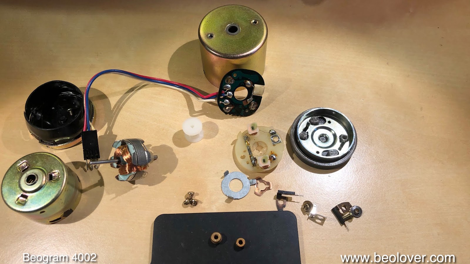
I took it apart to extract the bearings for oil infusion. As with most Beogram DC motors, this motor made squealing noises when I ran it from my bench supply. A clear indication of dry bearings, the most likely root cause for RPM variations. This shows the disassembled motor:
The bearings are the two small donuts on the black pad. I submerged them in motor oil and pulled a vacuum:
Immediately, strong bubbling started from both bearings. This indicates that the vacuum drew the air from the pores of the brass Oilite bearings. After about three days the bubbling stopped, indicating that the infusion process was complete. I extracted the bearings from the oil:
Then I reassembled the motor and installed it in one of my Beogram 4002s for an RPM stability test with my BeoloverRPM device.
This is the 24 hrs RPM curve I measured:
A very nice result. Pretty much as good as it gets with the Beogram 4002 DC motor! This unit is back in business!

1615CMBG4002MOT


Sunday, June 9, 2019

Beogram 4004 DC Motor Restoration

A Beogram 4004 DC Motor arrived from Germany for restoration. This shows the motor as received:

When I tested it, it ran very noisily, a clear case for oil infusion. I took the motor apart and extracted the bearings. Sadly, I forgot to take a picture of the disassembled motor....this shows the bearings submerged in oil after pulling a vacuum:
Immediately, vigorous bubbling occurred as the vacuum pulled the air trapped in the pores of the Oilite bearing material. This created room for oil to diffuse into the bearing. After about 3 days the bubbling stopped, i.e the bearing was again full of oil. I extracted the bearings from the oil and installed them in the motor. Then it was time for testing the RPM stability. I inserted the motor into one of my Beogram 4002s and ran it for 24 hrs while logging the RPM with my BeoloverRPM device:
This is the curve I measured:
this is pretty much as good as it gets with the Beogram DC motors, i.e. this motor is ready for duty again!


Wednesday, May 29, 2019

Beogram 4002 DC Motor Restoration

This post reports about the restoration of the 2nd Beogram 4002 DC motor (1st: see here) that recently arrived from the UK. This shows the motor as received:
I took the motor apart to extract the bearings for oil infusion:
The bearings are the two small brass donuts on the black pad up front. I immersed them in oil and pulled a vacuum. Immediately, vigorous bubbling started:
This indicated that the air was drawn from the porous Oilite bearing material making room for fresh oil to diffuse into the bearing. After about 48 hrs the bubbling stopped and I extracted the bearings from the oil:
I reassembled the motor and installed it into one of my Beogram 4002s. I ran it for 24 hrs measuring the RPM in 10s intervals with my BeoloverRPM device. This is the curve that was measured:
This is a pretty good result, but this motor seems to have slightly more variation than the first one. It is very likely that it will 'calm down' after it runs for some more time. The root cause for this kind of behavior may be that the orientation of the bearings improves over time as the motor runs. See here for a documented case, where the improvement happened over three weeks of running the motor. The joys of analog audio!...;-)


Friday, May 24, 2019

Beogram 4002 DC Motor Restoration

Two Beogram 4002 DC platter motors arrived from the UK. This post reports about restoring the first one. This shows the motor as received:
I disassembled the motor to get the bearings out:
The bearings are the two small donuts on the black pad upfront. These bearings are made from a porous material ("Oilite"), which has a limited amount of Oil infused when new. Over time this oil leaches out lubricating the shaft. When the oil is gone the shaft runs dry, which seems to be the case with most Beogram 400x motors these days.
I immersed the bearings in motor oil and pulled a vacuum:
Immediately, vigorous bubbling started. This is a sign of the air drawn out from the pores by the vacuum. Once the air leaves, the volume is filled with oil that diffuses into the material to replace the air ("nature abhors a vacuum"...;-). After about three days the bubbling came to an end and I assembled the motor for testing. 
I installed it in one of my Beogram 4002s and ran it for 24 hrs while monitoring the RPM every 10s with my BeoloverRPM device.
This is the curve I measured:
That is as good as it gets. This motor is ready for duty again!


Saturday, May 11, 2019

Beogram 4004 DC Motor Restoration: Yet Another Failure Mode - Strongly Oxidized Brushes

A Beogram 4004 motor arrived from Quebec for restoration. It ran a bit noisy, so the diagnosis was 'needs Oilite bearings re-infused with oil'. This shows the motor as received:
I took it apart to extract the bearings:
The bearings are the two small donuts on the black pad upfront. I started using a new 3D printed tool (grey plastic on the right that holds the bottom part of the motor housing) that allows me pressing out the plastic-type brush carriers of 1977 and later motor generations in their entirety. This reduces the risk of breaking the pickup coil leads or damaging the plastic carrier when extracting the bottom bearing.

I immersed the bearings in motor oil and pulled a vacuum. Immediately, vigorous bubbling occurred:
The bubbling indicates that the vacuum pulls out the air from the dry bearing pores. This makes room for oil to diffuse into the bearing, which then can lubricate the shaft of the rotor again.

After about three days the bubbling stopped and I extracted the bearings from the oil:
I re-assembled the motor and installed it in one of my Beogram 4002s for a 24 hrs RPM stability measurement with the BeoloverRPM device. It allows logging the RPM in 10s intervals over extended periods of time.

The blue curve in the graph below is the curve I measured:
Obviously, something was not right yet. Usually, if the oil infusion does not stop RPM drops entirely, one or more of the spark snubbers of the motor are gone. So I took the motor apart once more and installed unidirectional TVS diodes to replace the original spark snubbers. This shows the rotor with the original 'ring' of snubbers installed:
I unsoldered the connections of the devices:
One of the snubber devices was packed one with some glue. I had to gently heat up the area with my hot air blower to get the device off without destroying the rotor windings. Then I installed new unidirectional TVS diodes:
And tested the motor again. This yielded the green curve in the above graph. The drops were gone, as expected, but there were some new spikes to higher RPM. 

It turned out that the fix for this issue was to clean the brushes of the motor with a fiberglass brush. Upon closer inspection the brushes showed an unusual build up of carbonaceous residue in the area where they make contact to the commutator of the motor. My theory is that the motor was run for extended periods without proper spark suppression.

I put the motor back together again and measured another RPM stability curve (shown in red in the above graph). This curve is pretty much as good as it gets. In my experience the small variations that are still present will go away after playing the deck for a while (it seems the bearings and the shaft need some time to find perfect alignment after reassembling these motors). This motor is ready for duty again!