Featured Post

Beolover SyncDrive: DC Platter Motor Replacement for Beogram 4002 and 4004 (Type 551x and 552x)

Late Beogram 4002 and the 4004 (Types 551x and 552x), which have DC platter motors instead of the earlier synchronous AC motors usually suff...

Saturday, December 16, 2017

Beogram 8000: Last Beogram 8000 Project of 2017

An original owner of a Bang & Olufsen 8000 system from the eighties has sent me his Beogram 8000 and Beomaster 8000 components for restoration. These units are in very good shape but with some deterioration due to time in storage.

I am going to start with the Beogram as the Beomaster restoration is much more involved. Plus I will be able to spend time listening to the restored Beogram while I work on the Beomaster.

Here is the Beogram 8000 as I received it.


The rosewood, veneer trim is coming loose all around the frame. This can be fixed by carefully removing the veneer, cleaning off the old contact cement residue then gluing the trim back on.


I removed the top platter so I could loosen the lockdown screws of the floating suspension.


The next step is to open the Beogram up into its service position. This can be done with the dust cover and tonearm compartment cover in place but I prefer to carefully remove the lid assembly and store it away while I do the restoration. If the dust cover is out of the way it can't be accidentally damaged.

After disconnecting the three suspension spring clips I can open the Beogram cabinet.

Now I can start pulling out the various assemblies to work on them.

Typically at this point I am looking at replacing the tach disc on the small platter hub. The plastic printed tach disc is usually falling apart but this one is pristine.


This tach disc appears to have a lot of life in it. It will be up to the owner whether he wants to switch to the metal disc now or wait until this one starts to deteriorate. It is still something to see a perfect original.

There is a little bit of rust forming at the front part of the cabinet. That can be sanded clean and spray painted.


Here is the empty cabinet shell after the components have been removed.


I will store it a way along with the dust cover assembly for safe keeping.

Finally here are the assemblies removed from the Beogram that will have the bulk of the restoration work performed.


When I first started looking at this Beogram I noticed something was wrong with the tonearm. It was a little out of alignment and typically that just means the spring clip on the tonearm pivot needs to be adjusted. However, this tonearm was not responding to the spring clip. Something appeared to be broken.

A closer examination revealed that the outside pin of the tonearm pivot rod is missing. At some point in this Beogram's life the pin was broken.


Here you can see that the inside pin of the pivot rod is still intact.


This specialty part would be difficult to reproduce I think. Luckily I don't have to deal with that as I have exactly one spare Beogram 8000 tonearm left that I can get a replacement part from.

Here is the broken part after removing it from the tonearm assembly.


Note: The delicate Beogram 8000 phono wires pass through the tonearm pivot assembly and are right there where the repair work on this pivot rod is performed. Special care must be taken to not let the tonearm assembly get away from you and break a phono wire. That would be a huge pain to fix.


Here is the replacement pivot rod.


Here is the Beogram with the new pivot rod in place.


I will have to come back and tweak the adjustment screws on the tonearm assembly later when I get the electronic portion of the Beogram completed.

One thing I was anxious to take a look at on this Beogram 8000 was the tangential arm drive spindle nut. The last two Beogram 8000 units I have restored had broken spindle nuts...and so does this Beogram.


The break on this one isn't as bad as the previous two Beogram units. A repair is still necessary though.

I checked the usual places to search for the broken piece of plastic off the spindle nut. Unfortunately I am not able to find it.


So...no broken piece of plastic for a repair attempt. Believe it or not I am actually glad. Since the other two Beogram 8000 projects demonstrated this problem Beolover went to work on creating a replacement part. He has recently provided me with a few candidates to evaluate and I am expecting one of them to be the solution here.


Beolover sent me two metal candidates and three plastic printed ones. The replacement candidates differ in their inside diameter. The spindle nut needs to fit tight enough where there is no slop but not too tight to restrict movement.


Before I can run some real tests on the new part I have to work on the electronic part of the restoration. That is the next step.

Friday, December 15, 2017

Beogram 4000: Exchange of Black Painted Plinth with a Teak Plinth from a Beogram 4002

The Beogram 4000 that I am restoring right now came with a black painted plinth. Not sure why some people have the need to mess with a piece of iconic industrial design, but I guess "before you criticize a man, walk a mile in his shoes" (Steve Martin - the quote actually goes on: "That way, when you do criticize him, you'll be a mile away and have his shoes.'...an important point if you live in a country that has more guns than people...;-).

Anyway, here is a picture of the sad state of affairs:
As usual this plinth also had cracked guidance washers:
I removed the plinth. For this one has to remove the keypad since one of the bolts that hold it down is underneath.
Unfortunately, it is not possible to just take a plinth from a 4002 and bolt it into the 4000. Due to the slightly different sizes of 4000 keypad and the small aluminum panel that sits behind it, the metal fixtures that are glued to the plinth on the right side are different. You can see this here:

The top fixture is from the 4000, the bottom from the 4002. At the front of the plinth another small difference can be noted:
The tabs that hold the keypad down are a bit wider spaced in the 4000.

This means that the fixtures need to be exchanged. Removal is pretty easy since the glue gives when heated to moderate temperatures. I resorted to wrapping the plinths in aluminum foil and 'baking' them on the lowest setting in our oven (~85C) for half an hour. After taking them out, it was straight forward to remove the metal fixtures on both with a paint scraper that is pressed in-between the wood and the metal and then moved along until the parts are separated. The glue can be removed with Goo-B-Gone (thanks for this tip, Sonavor!).

One the parts are separated the most difficult part of the procedure begins: Butting them back together in a precise and straight way. This is critical, otherwise the plinth will not sit straight and of course that would be un-Beolovely!

In the past I used industrial strength adhesive tape for reattaching partially delaminated fixtures from plinths, and so this was my goto here, too. I put strips on the wood and trimmed them with a razor blade to match the footprint of the wood parts:
The key to attaching the fixture to the wood is to align it perfectly with the milled out groove that is in the lower part of the plinth. It turns out that the aluminum panels of the Beograms have exactly the same height as this groove, and so can be used as a 'natural' guide for reassembling the plinth!

I used the small aluminum panel of the Beogram and borrowed one from one of my 4002s to cover the entire right side of the plinth. Then I removed the tape backing on the front (and left the backing on on the side that no gluing wold occur while I aligned the fixture at the front) and pressed it in:

The Aluminum panels kept the fixture at exactly the same height front and back, ensuring a horizontal alignment.
Then I removed the tape backing from the strips on the side and pressed the fixture in:

Then I clamped everything together and let it sit for a while to ensure that the bond was solid:
Then it was time to bolt the plinth into the 4000. For this I used new 3D printed guidance washers:
They are available via the Beolover Shapeways store if you need some.

It is a good idea to get one manufactured in black to be mounted in the front center spot. This washer can be seen through the crack between the plinth and the aluminum panel if it is white.

This shows two of them installed:
Below the keypad -
and center front:
When I took out the original plinth, the mirror came off from the keypad cluster:
I am glad this happened so I had a chance to glue it back on in a lasting way with a couple dabs of epoxy:
Without this mirror in place it is impossible to see the strobe markings underneath the platter that are illuminated by the wonderful fluorescent orange bulb that is run at the AC grid frequency.
Allright, here is an impression of the Beogram with the new plinth on!
Beolovely! This looks so much better than the 'black ops' version! All that is left are a few final adjustments, and then it will be time for a first spin! I am looking forward to that! Playing a 4000 for the first time is always a special moment!


Wednesday, December 13, 2017

Beogram 4000: Replacement of the Sensor Arm Bulb with a LED Assembly

After replacing the cracked MMC cartridge mount in the Beogram 4000 that I am restoring right now, it was time to exchange the last remaining incandescent light bulb with a LED based assembly. This shows the bulb compartment extracted from the sensor arm:
This shows the wiring on the bottom side of the small PCB:
The LED assembly is based on a flexPCB circuit that imitates the power profile of a light bulb to not confuse the control electronics of the Beogram (which checks whether the bulb is functioning or not).
I extracted the bulb. This shows the bulb in comparison with the folded flexPCB based drop-in ready LED assembly 
This assembly is available to other B&O enthusiasts. If you are interested, send me an email of use the contact form on the right. This shows the LED assembly installed:
And in action:
The small 3D printed red wedge on top of the PCB ensures that the LED is in the right location to project its light properly through the lens in the bottom of the bulb compartment.


Tuesday, December 12, 2017

Beogram 4004 Type 5526: Packing for Shipment

I know the owner of this nice Beogram 4004 is ready for it to come home so I went through the packing steps and have it ready to take to the shipper.

The first steps I do in packing a Beogram is to remove the cartridge and lock down the floating suspension. The Beogram 400x series of turntables have three locking screws that are accessible inside the case if you remove all of the deck panels or from underneath the turntable if you don't want to open it up. In this case I preferred the latter.


Note: Only use a hand screw driver and don't over torque the screws. They just need to gently reach their travel limit and stop.

Now on to protecting the deck and tonearm for travel. The suspension is locked but the top platter and sub-platter could come loose during shipment should the box be turned upside down (a very real scenario).

I remove the top platter and pack it in a nice vinyl record shipment box.


I leave the sub-platter in place and cut a matching platter circle from packing foam. I also cut out packing foam to take care of the deck and tangential arm assembly. After aligning everything I glue my foam circle to the deck protective foam and fit it into place.


As you can see the dust cover closes over the foam packing insert. Now I put the turntable into a plastic bag and seal it up with clear packing wrap.


The Beogram 4004 is now secure where nothing should be able to move during shipment no matter what side the box is set on.

For outside protection I double-wrap the turntable using eggshell crate type shipping foam.


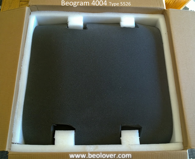
That entire bundle is set into my double thick walled shipping box. Instead of two separate shipping boxes I have been opting for a single box that has two layers of cardboard instead of the usual single layer. I cut and glue white shipping foam to the bottom and sides of the cardboard box.  The Beogram and platter fit nicely inside. Cables and cartridge boxes fit in the little compartments I created with extra foam blocks (also glued to the sides of the box).


The last two pieces are another eggshell foam top piece and a shipping foam lid.


This type of Beogram packing has worked well for me. The resulting size of the box is a little smaller than my old double boxed container so it is easier for the shipping guys to handle. That will reduce the chances of a drop.

It is always sad to see a project unit go but there is already another turntable waiting for restoration. Here's to a safe journey home.