That milestone has now been reached. Plugging in the Beomaster yielded no surprises and the expected red dot standby LED illuminated.
Pressing the PH (phono) button on the control panel illuminated the volume level and PH segments on the display.
The Beomaster appears to have power so it is time to measure the DC supply voltages.
First is the +5 VDC supply reservoir and the output of the +5 VDC regulator.
Very good. That check was pretty much redundant as the red LED dot would not have illuminated if the +5 VDC supply wasn't working. But I like to see what the actual voltage is.
Next are the ±15 VDC supply reservoirs and voltage regulators.
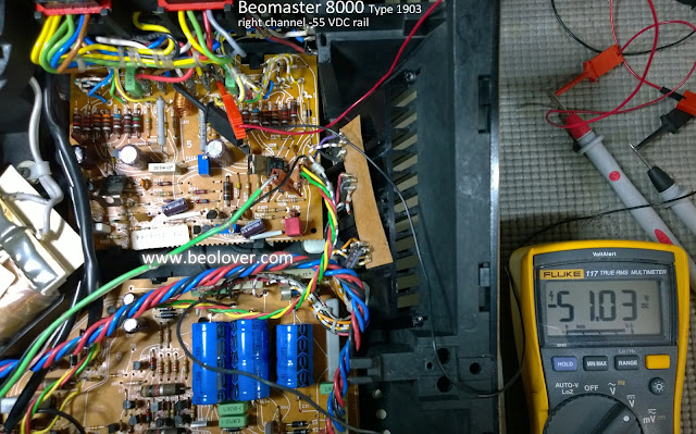
Those all check out. Now for the ±55 VDC rail voltages for the left and right channel output amplifiers.
All voltages are present and accounted for. That is a major milestone in the Beomaster 8000 restoration. From here it is to return and complete the work on the microcomputer and display boards. After that I will reassemble the Beomaster 8000 for functional testing.
With the power applied to the Beomaster I was able to see that there are some failed display segments. The plan was to rebuild those displays anyway so that confirms it is necessary.


No comments:
Post a Comment
Comments and suggestions are welcome!