After I finished the capacitor replacement on the final two boards for both the Beomaster 8000 from Canada and Texas my next task was to connect the components up and check out the power supplies. In my last post I successfully tested the power supplies on the unit from Canada. I am happy to say the Texas Beomaster has also reached that milestone.
There was a slight difference in being able to run the tests on the Texas Beomaster. When I completed the recapping of the microcomputer board I was not pleased with the state of the solder joints on that board. It had been worked on before and there were several places on the board where the soldering was not good. I didn't want to wait until I resoldered that board to check the power supplies. So I used one of my spare Beomaster 8000 microcomputer boards as a substitute in the Texas Beomaster for the power supply checks.
But first I had to reassemble components in order to try powering up the Beomaster.
Here is my substitute microcomputer board. It is a fully restored and known good board.
The Beomaster is ready to try powering up.
With my DMM connected to the +5 VDC regulator I plugged the Beomaster in to an AC outlet.
Success. The red LED standby dot is illuminated and I have +5 VDC at the power supply +5V regulator output.
I pressed the TP1 (tape 1) button on the control panel and the Beomaster came to life.
Continuing on the +5V, ±15V and ±55V supplies all checked out.
As on the Beomaster 8000 from Canada this is a big milestone. It's great to know that the supply voltages are all good on this Beomaster.
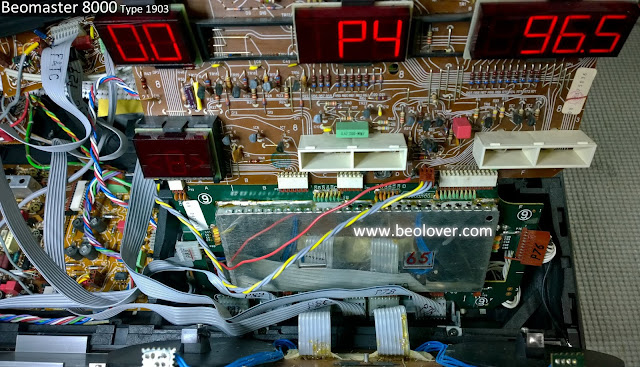
While the Beomaster was on I checked out the display board. Interestingly there were initially some segments out but later they started working. In the following photo I also turned on the Beomaster Filter button as indicated by the illuminated incandescent lamp.
I will have to check that out some more later. The next task on this Beomaster is to get its original microcomputer board resoldered and into shape where it is controlling the receiver.
Featured Post
Beolover SyncDrive: DC Platter Motor Replacement for Beogram 4002 and 4004 (Type 551x and 552x)
Late Beogram 4002 and the 4004 (Types 551x and 552x), which have DC platter motors instead of the earlier synchronous AC motors usually suff...
Subscribe to:
Post Comments (Atom)


I have the pleasure of seeing the restorer and his workshop west of Dallas, Texas recently. Very impressive and professional.
ReplyDelete