This post describes the work done on a Beogram 4002 that I recently received from a customer in Colorado. My initial assessment of the unit is posted here.
This shows the unit after removing the platter and the aluminum panels:

As usual, I started out by taking the DC platter motor apart for infusing the dried out motor bearings with oil. This shows the removed motor:

I disassembled it:

The shaft bearings are on the black pad upfront. I immersed them in synthetic oil and pulled a vacuum:

Immediately strong bubbling started. The bubbles represent air being drawn from the porous Oilite material due to the low pressure in the vacuum chamber.
This process usually takes 2-3 days until the bubbling stops. So in the meantime I focused on the other restoration tasks. The first step was cleaning and re-lubricating all the moving parts of the arm lowering and carriage translation systems. This shows everything still together:

I removed all moving parts:

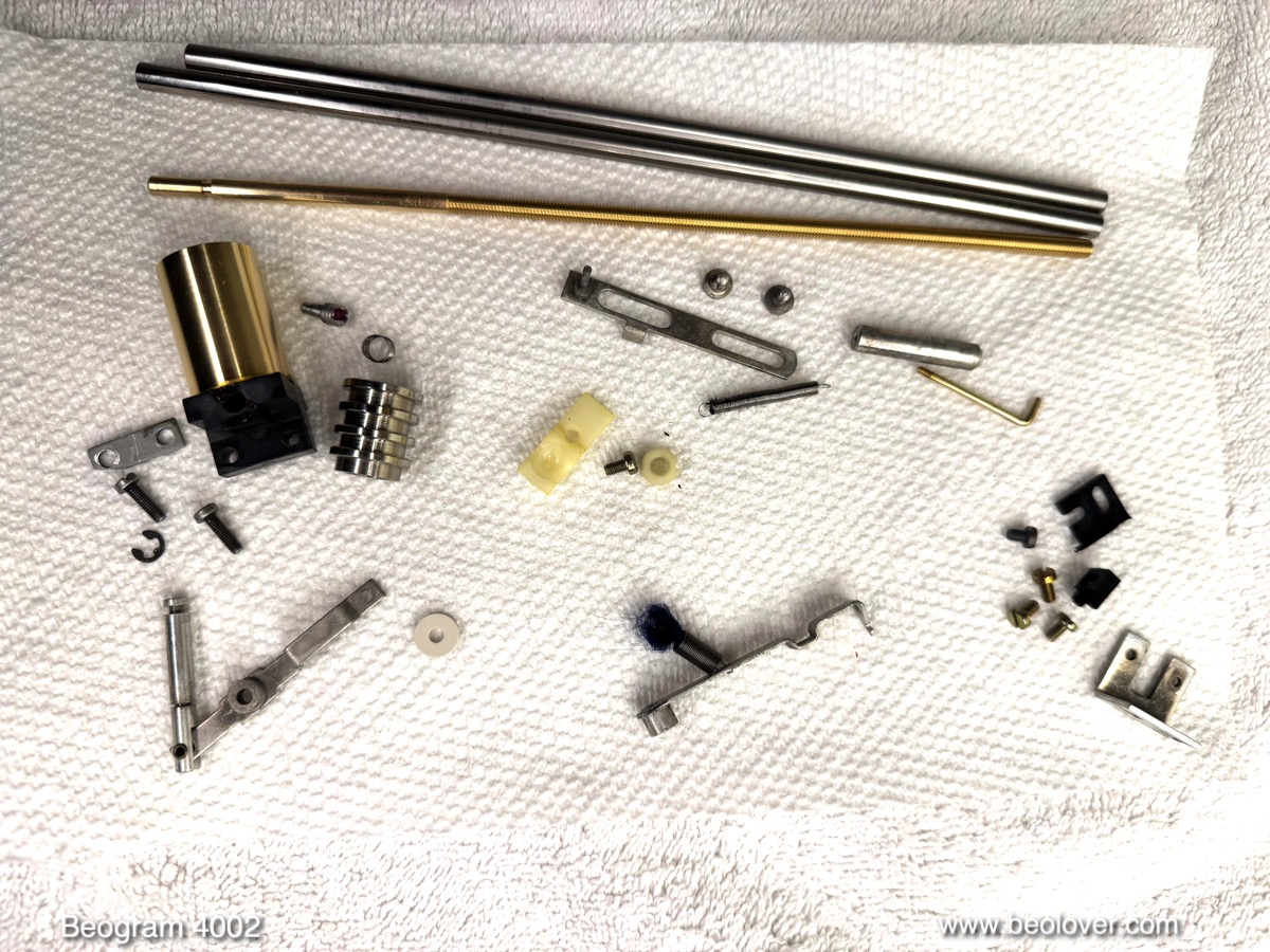
Here they are, pretty dirty and old lubricant encrusted:

I also took out the solenoid and extracted the plunger:

As usual, the plunger was a bit magnetized which I usually test with a ferrous setscrew. If it gets attracted by the plunger, it is magnetized:

After using my tape head demagnetizer on the part, the set screw was not attracted anymore:

Demagnetizing the plunger is an important restoration item since a magnetized plunger can cause delays in arm lifting during the automatic return of the carriage after playing through a record. Such delays typically cause the needle to be dragged across the platter until finally the arm lifts. Not a pretty sight when there is a newly rebuilt $800 cartridge on the arm!
Another to do item on the carriage is the replacement of the incandescent light bulb in the tracking sensor with a LED based assembly. This shows the original black bulb housing still in place:

I removed it. This shows it in direct comparison with the Beolover Tracking Sensor LED Light Source (for Beogram 4002 and 4004):

The replacement part is designed in a way that the LED is located in the approximate location of the bulb filament. This ensures an unproblematic replacement and adjustment process.
There is one more linkage in the arm lowering mechanism whose pivot point needs to be cleaned and re-lubricated: The linkage between damper and the actual arm assembly. It can be seen sticking out from the small v-cut visible from the back of the arms:

In order to get to this linkage, the sensor arm has to be taken out. Then the small locking washer can be removed and the linkage extracted:

As usual, the small copper plate that helps the arm move laterally when up came off after a light tug with my tweezers. I removed the degraded doublesided tape and glued it back into place with a dab of epoxy:

In the meantime the mechanical parts came back nice and shiny from the ultrasonic cleaner:
As usual, I installed a new damper gasket:

The original damper gaskets are usually hardened and/or deformed making the damping action inconsistent. This can lead to unhappy undamped arm lowering events and difficulties adjusting the lowering speed to a consistent behavior.
Another item that needed replacing in this Beogram was the spindle nut holder. The original part is shown on the right in the picture below. It has a crack at the bolt hole, usually a result of over tightening:

On the left the Beolover Spindle Nut Holder for Beogram 4000, 4002, and 4004 replacement part is shown.
This picture shows everything back in place:

A detail shot of the new spindle nut holder together with the LED tracking sensor bulb replacement:

I also installed a new precision machined Beolover Aluminum Carriage Pulley for Beogram 4002 and 4004:

Beolovely!
On to the circuit boards. I usually do the main board first. It is best to replace the two power transistors that are mounted on the solder side first. It makes it easier to place the new ones in the proper mechanical position with regard to the mounting holes. This shows one of them, 1IC1, which regulates the 21V power rail. It is usually a TIP120:

I normally replace it with a stronger TIP102 for enhanced longevity:

The small yellowish component soldered between its emitter and ground is a 100nF capacitor. These newer TIP components can cause a high-frequent oscillation on the power rail in this circuit configuration and the additional capacitance is necessary for quenching the oscillation. After replacing the other transistor 1IC4 with a TIP107 it was time to remove the PCB and focus on the remaining component exchanges. This shows the board in its original condition:

Here a detail shot of the 'RPM section' consisting of a Siemens relay for RPM switching and two trimmers for RPM tuning:

I usually replace all electrolytic capacitors, all power transistors, the RPM section and the sensor arm transistor, which often has lost some of its gain hampering the record detection mechanism. This shows the renewed board with the extracted components:

A detail photo of the new RPM section:

I usually replace the original single turn trimmers with modern 25-turn units that are encapsulated for a more consistent RPM adjustment. They need to be installed upside down so one can access their adjustment screws from the solder side of the board.
Next came the output board. This shows the original:

I usually replace the output relay, which is often oxidized or stuck and the capacitor that delays its action after the arm is lowered. I also install a switch (red) that allows connecting signal and system grounds in case there is ground hum on the output signal:

With the boards and keypad out, it was a good moment to address the degraded transport lock bushings

and clean out the enclosure from their fragments. These fragments need to be removed since they often get lodged under the floating chassis impeding its motion. So I removed the floating chassis leaving the enclosure empty for vacuuming:

Here a look at a few of the bushing fragments:

This shows the Beolover Transport Lock Bushing Set for Beogram 4000, 4002, and 4004:

They are designed with a maximized internal diameter and minimized thickness to allow for an improved adjustment range of the floating chassis and to give it a large lateral motion range. This prevents banging of the chassis into the lock bolts when it is agitated by accidentally touching it etc...
The bushings are designed in two parts, this makes their installation a snap. Simply push one half in from the bottom

and the other from the top:

Sometimes the orifices are a bit larger than usual, and then a drop of super glue gel on the vertical parts can help hold them in place. This shows one of the bushings around one of the transport lock bolts:

After re-installing the chassis with the new bushings I replaced the original reservoir capacitor. In this case it was a dual capacitance unit since this Beogram was fitted with a separate power supply for the optional CD-4 output boards that could be installed back then:

I removed the part including the round rectifier that is bolted to it

and replaced it with a Beolover Main Reservoir Capacitor for Beogram 4002 and 4004 (Types 551x/552x):

The part can be used to replace both single and dual capacitance reservoir capacitors. Simply transfer the wires to the labeled solder pads and bolt the part in using the provided red alignment guide.
Inspired by past restoration experiences I always check on the fuses in the small black box in front of the transformer:

They often loose their seal at the end caps and come apart when one takes them out of the fuse holders. In this case, however, I found that someone already had replaced them with a 3.5A

and a 2A fuse:

This is a bit dangerous and would have probably led to a transformer meltdown in case of a real short circuit. That is why they put a sticker on the fuse box specifying 250mA slow blow ("TRÄG") fuses!...;-):

I put in a set of new fuses with the correct value and then plugged everything back together for testing. But first I still had to adjust the newly installed biasing trimmer for the sensor transistor. It has to be adjusted to yield 4V at the collector while the board is installed. Therefore, it has to be briefly soldered to the solder side of the board for its adjustment:

After it was set I moved it over to the component side behind the sensor transistor:

Then it was time to replace the remaining incandescent bulbs with LED assemblies. First came the sensor arm bulb. It sits in the small inserted compartment at the end of the arm. This shows the little compartment pulled out revealing the bulb:

Next to it is the Beolover Sensor Arm LED Light Source (for Beogram 4002, 4004 and 4000) with its alignment aid. This shows it installed:

And in action:

The warm white LED produces an incandescent-like sheen through the B&O logo. Beolovely!
The remaining two bulbs were in the RPM panel above the keypad. This shows it removed and flipped on its front:

Behind the two covers are the bulbs that illuminate the RPM adjustment scales:

The two small green boards are the Beolover RPM Panel LED Backlights for Beogram 4002 and 4004 (Types 551x/552x). They solder directly to the points where the bulbs were connected:

Here a detail shot. They essentially act as an extension of the board:

The LEDs produce a nice warm incandescent sheen that looks very similar to the original bulbs:

Next I re-installed the wood frame that I had glued back together. This Beogram came with three metal and two plexiglass plinth guide washers. I replaced the cracking-prone plexiglass types with new Beolover washers (white, upfront in the picture):

In the meantime the motor bearings had completed their infusion process and the bubbling had stopped completely. I extracted them from the oil

and re-assembled the motor. Then it was time for running a 24 hrs RPM stability test using the BeoloverRPM device:

In its 'slow' mode it is able to log the RPM every 10 seconds into a computer serial port. This is the curve I measured after about 24 hrs:

This is a great curve and as good as it gets. This motor is back in business!
It is always interesting to also look at wow and flutter, the short term RPM fluctuations caused by the feedback controlled DC motor. This can be done using the 'fast' mode of the BeoloverRPM:

In fast mode it will send an RPM measurement every time a platter rib passes under the sensor. This high resolution data allows seeing the feedback control mechanism in action. This graph shows a measurement over about 45 rotations of the platter (~1.5 min runtime):

The observed graph is a superposition between a slow sine-like wave and a fast repeating pattern. The fast pattern is a measurement artifact caused by the slightly varying distance between the ribs around the platter. It repeats exactly every 24 data points, corresponding to the number of ribs.
This is a manufacturing 'defect' that can be regarded as a 'finger print' that is unique to each platter. This particular platter has a very clear pattern meaning that the variation of the rib distances is smoothly in- and decreasing around the platter.
The sine-wave like superimposed pattern reflects actual RPM variations. An evaluation of this line shape reveals RPM variations of about 0.1%. This is about double the <0.05 number stated in the service manual, but this may well be a result of the entirely different measurement methods used here and back in the 1970s, when digital technology was still in its early beginning and wow and flutter was measured with test records and analog frequency analysis. In any event these variations are much too small for humans to notice. Only RPM variations above about 0.7% can be detected by most people.
With the platter running properly again it was time to focus on the remaining adjustments. The first step is usually to align arms, platter and subchassis to achieve a 23 mm top-of-the-arms-to-platter distance and to get the platter and arms parallel, while leveling the subchassis to get the platter flush with the surrounding panels. This can be a pretty tedious and iterative process, depending on how out of alignment things are. I usually start with getting the aluminum panels properly aligned and settled on their alignment pins together with the keypad. Then I get the arms parallel and in 23 mm distance with the aluminum panels. Then the platter can be adjusted to be in the same distance. If everything is done right at that point everything is parallel and in the right distance.
Once this is squared away the tonearm adjustments can be done. I usually start by replacing the flimsy locking washer that holds the counterweight adjustment screw in place

with a square M3 nut and a washer:

This allows locking in my calibration that it can survive the rigors of shipping. Before I calibrated the tracking force, I adjusted the arm lowering limit. The needle should not hit the lower rungs of the platter ribs when down without a record but be significantly below the top ribs to make sure the arm is completely free when the needle is in the groove:

Then I adjusted the tracking feedback to get about ~2-3 rotations after lowering before the carriage starts moving:

And finally I calibrated the tracking force to get 1.2g weight at a dial setting of 1.2:

The weight dial is notoriously imprecise, so it is best to simply measure the weight once in a while with a digital gauge and just set the wheel to whatever setting is required to get the proper weight.
The final step before trying this deck out for the first time was to replace the original DIN plug. This unit came with the RCA adapter taped to the output plug, indicating that there may have been some contact issues in the past:

Indeed the original plug was pretty oxidized:

I installed a nice new all-metal DIN5 with gold plated terminals:

Beogolden! And so it was finally time to give this newly restored Beogram a first test spin! I selected one of my favorite records released by the German Musik produziert im Schwarzwald (MPS) label, Oscar Peterson's lush "Motions & Emotions" record, which he recorded in 1970 together with Claus Ogerman who conducted and arranged the orchestra section. My pressing is a 1972 gatefold re-issue with BASF (MB 20713). I really like their interpretation of Antonio Carlos Jobim's Wave. Definitely euphoric enough to celebrate a newly restored Beogram! Bemotions!...;-)
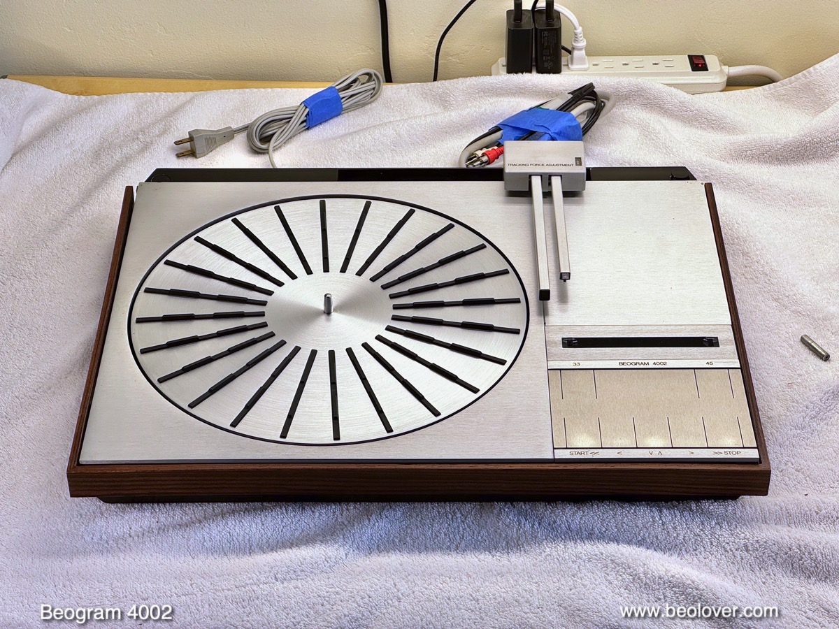
Beautiful!:

I will now play this deck for one-two weeks to make sure there are no intermittent issues, and then it will be time to send it back to my customer in Colorado!






.jpg)


