Featured Post

Beolover SyncDrive: DC Platter Motor Replacement for Beogram 4002 and 4004 (Type 551x and 552x)

Late Beogram 4002 and the 4004 (Types 551x and 552x), which have DC platter motors instead of the earlier synchronous AC motors usually suff...

Showing posts with label RSBC9000. Show all posts

Tuesday, July 28, 2015

Beocord 9000: Restoration of the Peak Program Meter Scale Illumination

While the scale illumination light bulb was still working in the Beocord 9000 display that I am rebuilding right now, my customer decided to replace the bulb anyway to make sure that there are no unwanted surprises during return shipping. I can only agree since these light bulbs have a tendency to break their leads of during high vibration-situations (think speeding FedEx truck and a bunch potholes...;-). Once one is in there, I think it is best to simply replace everything and be done with it.
I did this procedure already once in the last Beocord 9000 that I rebuilt, which had a broken bulb.

Here are a few pictures to document the process for this particular unit:
This photo shows the original light bulb held in place by the 'cork' that sticks through the PCB

and from the back:
This is the PCB that I implanted. It is the same that I use in the Beogram 4000 to replace the position-scale incandescent bulbs.
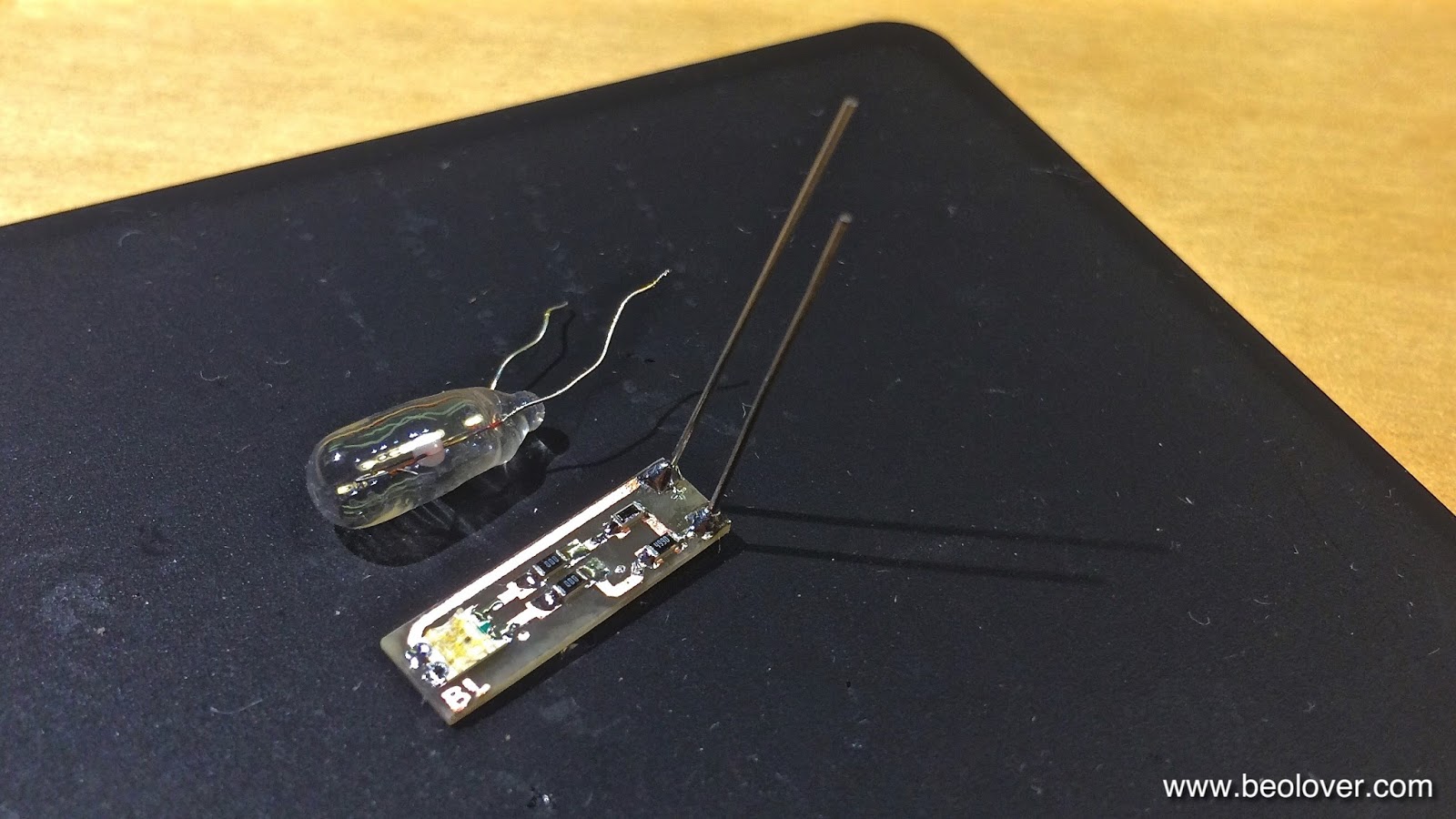
It has almost the same width as the 5 mm bulb that they used in the Beocord 9000. I only use one red-green LED on the board for this application, i.e. I bridged the second LED position with SMD jumpers ("000"). It is important to replace incandescent bulbs with red-green LEDs if the light is being filtered or reflected by red or green features (like in this case where the scale is both green and red).

This picture shows the LED board inserted into the bulb space.

And from the back. It can directly be soldered to the solder points of the bulb, the polarity matches:

Here is a picture of the test drive:

On to the 7-segment display.


Monday, July 27, 2015

Beocord 9000: Restoration of the Peak Program Meter with SMD LEDs (III)

This is the third installment of my report on how to rebuild the peak program meters (PPM) of a Beocord 9000. The first two posts report on the installation of SMD LEDs to replace the original faulty LEDs on the PPM PCB, and the re-attachment of the plastic covers. This post demonstrates the installation and brightness adjustment of the rebuilt PPM.
The first step was to replace the original current limiting resistors with the correct values for the modern SMD LEDs. Modern LEDs typically need much less current and achieve higher brightness than the original LEDs. This is reflected in the much larger resistor values that my initial experiments yielded to achieve similar or slightly increased brightness with the new LEDs. The original values were 180 Ohm for the red and 120 Ohm for the green ones. The SMD types required 470 Ohm for red and 330 Ohm for green for slightly enhanced output (see first post). The resultant currents were in the 10 mA range, while the original LEDs easily draw 40 mA, while having a lower intensity.
Here is a picture of the original resistor bank (the 8 leftmost resistors)
This shows the new resistors installed. Despite the PPM having 16 LEDs there are only 8 resistors. This is due to the fact that the two left and right PPMs are multiplexed at 60 Hz, i.e. only 8 are on at a time. This is seen in the signals of the two common anodes (pin 1 and 2 on the display board) which each drive one of the PPMs:

This shows the new resistors installed:


And here after installation of the rebuilt PPM:
And in action:

It turned out to be a good idea to fix the two display boards in sequence, i.e. leave one in while taking out the other. this allows to realign the one that was out with the one that is still in when putting it back. That way it is easy to get it back into the right position that it fits perfectly into the plastic bezel. Another helpful thing to do is to mark on the headers of the displays how far they were inserted into the PCB. This is important to get the right slant of the displays that matches the cover.
On to replacing the scale illumination bulb with a red/green SMD LED.

Friday, July 24, 2015

Beocord 9000: Restoration of the Peak Program Meter with SMD LEDs (II)

The 24 hrs test of the rebuilt Peak Program Meters (PPM) of the Beocord 9000 display that I am rebuilding was successful:


So I set out to reattach the red-green covers. Encouraged by my recent rebuild of a Beocord 9000 counter display, I decided to rely on melting the plastic posts of the red-green covers with my soldering iron set to 200C to recreate the original attachment method. First I needed to clamp the display together, however, to ensure that the covers would make a tight bond with the PCB to avoid light escaping through cracks at the bottom:

I applied the clamps in a way that the cover posts were still accessible and then I melted them by rolling the solder iron tip cone over them. This worked quite nicely:

When I cleaned the PCB with ethanol after soldering the SMD LEDs, the glue that held the light guide down dissolved. This told me that this clear glue was most likely some kind of polyvinyl ester based carpenter glue. So I used 'Aleene's Original Tacky Glue', which is my mainstay for bonding speaker foams to the cones. This glue dries clear, recreating the original look of the bonds:

After the glue was hardened, I put the display again to a 24hrs test to ensure that nothing bad happened during the reassembly:

What a beautiful design! I can't wait until I can make a test-recording with this deck using these lovely big rebuilt PPMs.


Beocord 9000: Restoration of the Peak Program Meter with SMD LEDs (I)

While I am waiting for the pinch roller for the Beocord 9000 I am finishing up, I started working on another 9000 that needs the displays rebuilt. Cassettes are definitely back! I hope they will start manufacturing new tapes again (and SONY decides to restart the production of the Walkman II...but that is an entirely different story...;-).
Anyway, here is a picture of the sad state of this display:

Not shown here, but the TIME CAL bulb is also dim, like on the other 9000. I decided to attack the VU or 'peak program' meter (PPM) first, since I never did this type of display before. Beolover excitement, no doubt! After opening the Beocord up, the first step is to remove the display bezel that covers the boards and also holds the translucent windows:
After taking the bezel off:
The I unsoldered the PPM board:
The next step was to remove the plastic covers. It turned out that there are black cardboard strips inserted between the covers and the light guide for the scale illumination:
The plastic covers were fixed to the PCB by melting their protruding plastic feet and flattening them, which creates round shaped 'seals':
These must be removed before the covers can be lifted:
I decided to leave the light guide in. Here is a picture after taking the covers and strips off:
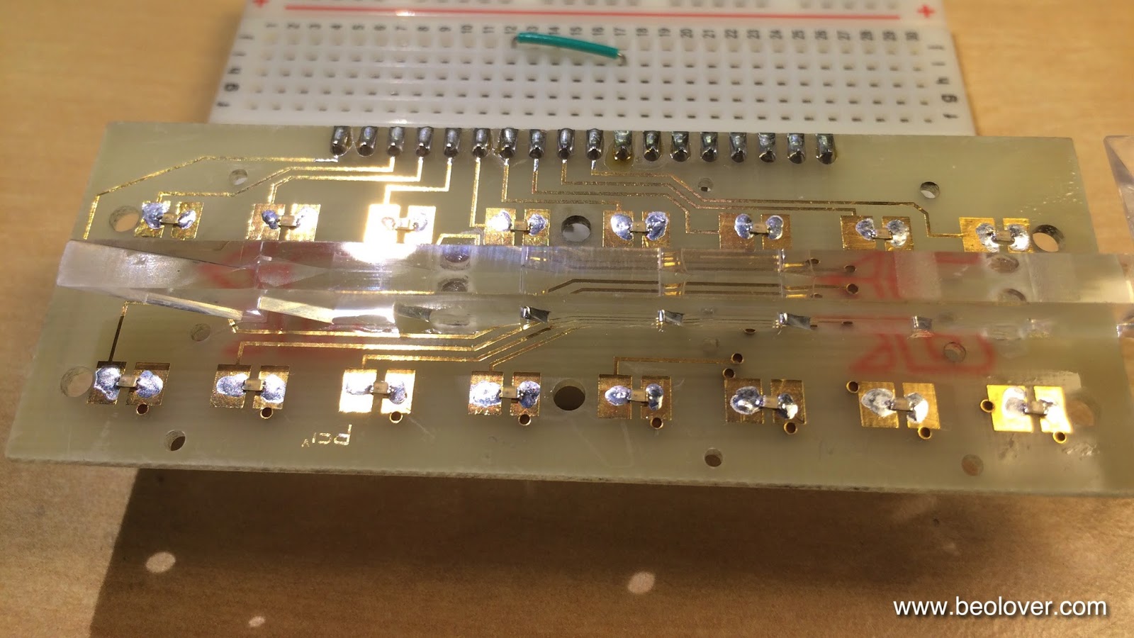
For the fun of it, I piped some light in from the side where the scale illumination bulb sits. One can see nicely that the triangular cutouts in the bottom act as mirrors that reflect light to the positions where the scale numbers are:
After playing with this I started working on the rebuild. The first task was to determine the right resistors for the new SMD LEDs. First I determined the values needed to achieve an identical brightness to the original LEDs. For this I replaced a red and a green one of the four broken LEDs with SMD LEDs (Newark 75K1441 (red 14MCD 2.0V) and 75K1440 (green 18MCD 2.1V):
then I rigged the setup with resistors and ran it:
And with covers on:
It turns out that values of about 1k Ohm for red and 670 Ohm for green at 6.2V yield similar brightness. Note that the red LEDs had a similar brightness difference as the green ones, but the camera was not able to show this very well.

My client decided to ramp the brightness a bit up that the displays are better visible in brightly lit rooms. So I determined values that will make them match well with the higher brightness 7-segment display of the counter and indicator light SMD replacements that I usually use.
Here is a picture of the higher brightness version in comparison with the original LEDs:
The values that do the job are 330 Ohm for green (yielding 12.6mA) and 470 for red (9.4mA)
After this tests, I replaced all LEDs with SMD versions:

And running at 6.2V with the above resistor values in series:

Beautiful!! I will let this run for 24hrs before I reattach the covers to make sure that there are no problems.