While I am waiting for the pinch roller for the Beocord 9000 I am finishing up, I started working on another 9000 that needs the displays rebuilt. Cassettes are definitely back! I hope they will start manufacturing new tapes again (and SONY decides to restart the production of the Walkman II...but that is an entirely different story...;-).
Anyway, here is a picture of the sad state of this display:

Not shown here, but the TIME CAL bulb is also dim, like on the other 9000. I decided to attack the VU or 'peak program' meter (PPM) first, since I never did this type of display before. Beolover excitement, no doubt! After opening the Beocord up, the first step is to remove the display bezel that covers the boards and also holds the translucent windows:

After taking the bezel off:

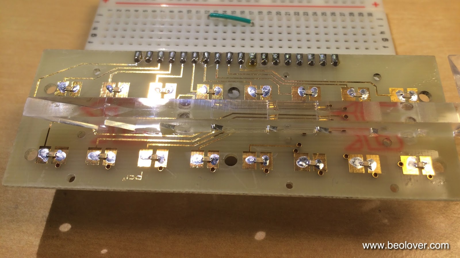
The I unsoldered the PPM board:

The next step was to remove the plastic covers. It turned out that there are black cardboard strips inserted between the covers and the light guide for the scale illumination:

The plastic covers were fixed to the PCB by melting their protruding plastic feet and flattening them, which creates round shaped 'seals':

These must be removed before the covers can be lifted:

I decided to leave the light guide in. Here is a picture after taking the covers and strips off:

For the fun of it, I piped some light in from the side where the scale illumination bulb sits. One can see nicely that the triangular cutouts in the bottom act as mirrors that reflect light to the positions where the scale numbers are:

After playing with this I started working on the rebuild. The first task was to determine the right resistors for the new SMD LEDs. First I determined the values needed to achieve an identical brightness to the original LEDs. For this I replaced a red and a green one of the four broken LEDs with SMD LEDs (Newark 75K1441 (red 14MCD 2.0V) and 75K1440 (green 18MCD 2.1V):

then I rigged the setup with resistors and ran it:

And with covers on:

It turns out that values of about 1k Ohm for red and 670 Ohm for green at 6.2V yield similar brightness. Note that the red LEDs had a similar brightness difference as the green ones, but the camera was not able to show this very well.
My client decided to ramp the brightness a bit up that the displays are better visible in brightly lit rooms. So I determined values that will make them match well with the higher brightness 7-segment display of the counter and indicator light SMD replacements that I usually use.
Here is a picture of the higher brightness version in comparison with the original LEDs:

The values that do the job are 330 Ohm for green (yielding 12.6mA) and 470 for red (9.4mA)
After this tests, I replaced all LEDs with SMD versions:
And running at 6.2V with the above resistor values in series:

Beautiful!! I will let this run for 24hrs before I reattach the covers to make sure that there are no problems.
No comments:
Post a Comment
Comments and suggestions are welcome!