Featured Post

Beolover SyncDrive: DC Platter Motor Replacement for Beogram 4002 and 4004 (Type 551x and 552x)

Late Beogram 4002 and the 4004 (Types 551x and 552x), which have DC platter motors instead of the earlier synchronous AC motors usually suff...

Showing posts with label 2020SVRBM4400-01. Show all posts

Monday, July 27, 2020

Beomaster 4400 Type 2419: Personal Project: Reassembled and Ready for Listening Tests

I decided I would reassemble this Beomaster 4400 and start performing some listening tests with it before I do any performance testing and before I complete the cosmetic restorations.

The reason for that is I want to get my second Beomaster 4400 started and completed as soon as possible...while the soldering iron is hot :-).  That way I can test and compare both units together.

The second Beomaster will also require a little bit of cosmetic repairs.

First though I must fix the power on lamp on this Beomaster unit.
Here is the power on lamp assembly housing. I is a black plastic lamp housing that fits onto a metal bayonet that is part of the lamp lens inside the front of the cabinet. It just pulls off the bayonet for access to change the lamp.


The lamps fit really tight inside the housing to it takes some careful pulling to remove one.

Once the lamp was replaced the power on lamp worked again as well as the radicator lamp.
That makes sense as the power for the radicator lamp comes through the power on lamp.


Moving forward with the reassembly I installed new cabinet feet on the Beomaster cabinet bottom cover.  These Beomaster 4400 cabinet feet are usually rusty and flat.

On this Beomaster the feet are a little smashed down and one foot is missing. No rust though. That is a welcome site.


The replacement feet are much better and have a metal tube for the screw so the rubber doesn't get flattened out if somebody over torques the mounting screw.


I reattached the front slider control bar then the bottom plate and the top cover. This Beomaster is ready for some listening tests.


After I recap and change trimmers in the second Beomaster 4400 I will return and do some cosmetic touch ups on this one. The rosewood cabinet looks nice in the photos but the finish is a little dull. Plus there is the small chip on the left side. I also need to order a cover plate for the FM preset tuning dials. I can get that from Martin Olsen's Beoparts store.


Sunday, July 26, 2020

Beomaster 4400 Type 2419: Personal Project: Initial Power Checks

I couldn't end the day with just having the board restoration work complete.

I am always curious whether the audio components will actually work now.

First step was to reinstall the preamplifier and FM boards.


The Beomaster is ready to power on. Like I always do with this type of amplifier I connect the power cord to my variac, ammeter, voltmeter and dim bulb test device.  That device will protect against any hidden short to grounds on the power signals and it will tell me if something is drawing too much current.

In this case...I got nothing. No lights, no voltage on the power supplies.


After a bit of investigation I discovered that one of the AC cable wires was not connected internally in the Beomaster.  That explains that.

I checked the other wires around it and checked for any shorts. Other than the disconnected AC wire everything else looked fine.

Here is my repair of the broken wire.


That looks much better.

On the second round of the power checks I still don't get any lights illuminating on the Beomaster 4400 but I do have power on the supplies.

Here are the +15 VDC and +35 VDC supply checks


and here are the ±35 VDC rail voltage checks


It looks like the Beomaster 4400 is ready for a quick listening check.

I did a quick, initial setting of the idle current for the output amplifiers by adjusting the left and right channel trimmers to get 10mVDC across the respective channel emitter resistors.


Once those were adjusted I connected an iPod Nano to the Tape 2 source input and used a pair of headphones to check if I had sound.

Success!


I connected up an FM antenna to the Beomaster 4400 antenna input and tried tuning a station.
Another success.  The FM tuner section is working great. The tuning indicator and stereo lamps do come on as well.


So for certain the Beomaster 4400 power on lamp is not working and the lamp that illuminates the radicator (the FM signal strength meter) is also not working.

I am not sure about the overload lamp but I can test that when I replace the power on lamp.

Saturday, July 25, 2020

Beomaster 4400 Type 2419: Personal Project: Preamplifier board and FM boards

The remaining boards requiring some recapping restoration are the preamplifier board and the FM boards of the Beomaster 4400.

Again, the previous post here, show the before state of the boards.

On the preamplifier board I also replaced the six, single-turn trimmers for the Phono, Tape 1 and Tape 2 source inputs.

Here is the preamplifier board after the restoration work -


Here are the three FM boards (FM1: Tuner, FM2: IF Section , FM3: Stereo Decoder and Indicator).
There is one 10uF, 10V tantalum capacitor in the FM1: Tuner board. I measured it and it is right on 10uF so I left that capacitor alone for now.


...actually that photo is a little premature.  The board still needs a 1uF and 0.47uF capacitors as shown added in this next photo.


Now for the big step of reinstalling the boards and setting up the first power on test of this Beomaster.

Beomaster 4400 Type 2419: Personal Project : Main PCB Recap, New Reservoir Capacitors, New Trimmer Resistors

It may look low profile and small but recapping a Beomaster 4400 is quite a big desoldering and soldering task.

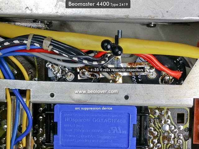
I finished replacing all of the electrolytic capacitors and trimmer resistors on the Beomaster 4400 main board. I also installed an arc suppression device like I installed on the previous Beomaster 4400 restoration project. The purpose of that device is to provide extra protection to the Beomaster power switch contacts.

Here is the Beomaster 4400 after the recapping (the before photos are in the previous post)


Here are some closer shots of the inside of the Beomaster 4400 after the recap.


and here is a closer look at the reservoir capacitors and the arc suppression device.


With the main board and chassis completed I can move on to the three FM boards and the preamplifier board.

Monday, July 20, 2020

Beomaster 4400 Type 2419: A Personal Project

Whenever I do a restoration on a Bang & Olufsen audio component I find myself wanting to keep it for myself.  It makes sense seeing how these units we restore are units we also like ourselves here on the blog.

A few years ago I had my own working Beomaster 4400 that I purchased in working order. Since it worked great I decided to leave it as is and just use it until it started to fail.  I got two good years out of it before I started to notice a degradation in performance.  At that point I put it away for later restoration when I had time.

After my last Beomaster 4400 restoration project I was reminded how I liked this receiver so I opened up a spot in my restoration schedule to do one of mine.  Truthfully, I plan to do two for myself.  That is because a few months ago I acquired another Beomaster 4400 unit that is from one owner and looked to be a great restoration candidate.

So I will begin with the latest acquisition then move to the first unit.

Here is how it looks having just opened it up.


It is pretty clean overall. You can immediately tell that this unit was stored well and came from a smoke-free environment. The lenses on the controls are still clear.

There is some sort of black gunk on the metal frame but I should be able to clean that off.


The left and right sides of the rosewood cabinet have small chips. One is still hanging on so that will be an easy repair. The other side is gone so I will have to fashion a matching piece out of some rosewood veneer I have in my shop.


The color on the cabinet is good. It doesn't appear faded so after the repair of the cabinet dings a little sanding and refinishing should make it look new again.

Inside the Beomaster 4400 circuitry looks original as expected. The front controls all operate smoothly (without power applied).


Very nice.

Removing the smaller boards I don't see any signs of burned or broken traces.


Here is the Beomaster stripped down where I will begin work on the restoration.


Here are the three FM modules and the preamplifier removed and ready for recapping.


As clean as this Beomaster 4400 unit is I am hoping that I won't have to dig in to the front panel components like I did on the previous Beomaster 4400 project.

I should be able to do most of the cleaning, solder reflowing and capacitor replacement without much disassembly this time.

The power switch on this unit seems to be in good order so I will only have to attach my arc suppression device.

The previous Beomaster 4400 project used up quite a few of my restoration components for these receivers so I ordered more from Mouser last night and they should arrive tomorrow.