Featured Post

Beolover SyncDrive: DC Platter Motor Replacement for Beogram 4002 and 4004 (Type 551x and 552x)

Late Beogram 4002 and the 4004 (Types 551x and 552x), which have DC platter motors instead of the earlier synchronous AC motors usually suff...

Sunday, May 9, 2021

Beogram 8002 From North Carolina: Replacing the old capacitors

 As we do with all vintage audio equipment over thirty years old...the original electrolytic capacitors are replaced with new ones. On the Beogram 8002 I like to use high quality Japanese brands like Nichicon and Panasonic for capacitance values greater than 4.7uF and German made WIMA MKS capacitors for capacitance values 4.7uF and smaller.  All of the replacement capacitors are rated for 105°C and above.

Starting with the two electrolytic capacitors on the Beogram 8002 chassis (for the +5 VDC regulation) here are the before and after photos.

Before


After


I moved to the transformer box next.  There is a non-polarized capacitor in the transformer box that connects to one side of the platter drive.  The original capacitor was too large to fit onto the already filled up main circuit board so the B&O engineers placed it in the transformer box.


This capacitor varies by Beogram 8002 Type. For the Type 5633 the value is 27uF, 55V and is non-polarized.  I am replacing it with a Nichicon 33uF, 63V, 105°C non-polarized capacitor.  The modern capacitor has a much smaller physical size so I mounted it on a 3D printed insert.


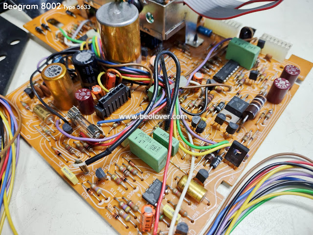
The main circuit board was next.

Before


After...I reused the three-pronged negative lead base from the original C27, 2200uF, 40V capacitor on the new Nichicon C27 capacitor. That makes things so they mount back onto the board like the original C27 did.


The last capacitor to replace is the 47uF, 10V electrolytic capacitor in the metal box that contains the Beogram 8002 microcomputer.  The capacitor there is C28 and filters the +5 VDC power to the microcomputer IC.

The original C28 had come apart at the seams.


No +5 VDC power for this microcomputer.

Because of the cramped space and the fact that the negative (ground side) of capacitor C28 is difficult to get to I just cut it out rather than try to negotiate the soldering iron.


Before installing the replacement C28 capacitor I removed the Beogram microcomputer IC.
I like to change out the socket for the microcomputer and while the device is removed it makes cleaning up and installing the new C28 capacitor easier.




Here is the new C28 installed.

Component side


Trace side


I showed the trace side along with the component side for C28 to show that the negative lead has to be soldered on both sides of the board.

In the next post I will finish up the circuit boards by installing the new microcomputer IC socket, re-flowing solder joints on the main board and repairing the broken wiring on the phono output, muting circuit.


No comments:

Post a Comment

Comments and suggestions are welcome!