Featured Post

Beolover SyncDrive: DC Platter Motor Replacement for Beogram 4002 and 4004 (Type 551x and 552x)

Late Beogram 4002 and the 4004 (Types 551x and 552x), which have DC platter motors instead of the earlier synchronous AC motors usually suff...

Friday, August 31, 2018

Beomaster 8000 (Type 1903): Output amplifier assembly testing and adjusting

The output amplifier assembly bench testing and adjustments went smoothly.  I like testing the output amplifier boards stand-alone, outside the Beomaster cabinet.  It is a pain to take these assemblies out and then re-install them so I prefer testing them by themselves to make the initial service manual adjustments.  That way if any components are bad I already have the board available for trouble-shooting and component replacement.

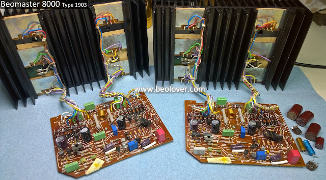
Here are the two sets of output amplifier boards I had to test and make initial adjustments on (the two boards from the Canada Beomaster 8000 and the two boards from the Texas Beomaster 8000).


As a reference I have one of my spare output amplifier assemblies. I start with the spare board in getting my bench test setup.


I use two 60V bench power supplies to supply the ±55V rail voltages for the output amplifier board.
As a protection measure each supply is set to limit its current output to 150mA.  A properly adjusted Beomaster 8000 output amplifier will draw around 100mA to 120mA when the board is powered up and the no-load current is set. If a fault exists that attempts to draw too much current, these supplies will shut down before any collateral damage can occur.

I use a 30V bench power supply to provide the +15V to the board that controls the output amplifier being on or off.

The ±55V voltages are applied first.  This is done slowly to monitor the current draw.
With the board off, the +15V supply at zero volts, the ±55V supplies should draw between 20mA and 30mA.


When the +15V supply is applied the output amplifier will be on and the current draw is around 100mA. 


The no-load current adjustment is performed with no speaker load and zero volts on the audio inputs. When the output amplifier is fully powered on and is not amplifying any audio signal the voltage across the output emitter resistors should be at 18mV.

For the DC offset adjustment the speaker load is applied and the audio input signal remains at zero volts. The voltage across the speaker load is measured and adjusted to 0V ±5mV.


After confirming the test setup and procedure with the spare board I started with adjusting the left channel output amplifier board for the Beomaster from Canada.


As I started to apply the +15V control voltage I monitored the ±55V supplies. With only about 3V applied from the +15V supply my ±55V supplies were already at 120mA


That can happen on a newly restored board and means the no-load current adjustment trimmer needs to be dialed down.


I use the expected 100mA ±55V supply current draw as my guide to adjust the no-load current trimmer as I adjust the +15V supply up to its full voltage.


When that is reached I should have about 18mV across the emitter resistors.


I followed that up with the DC offset adjustment. To do than I turned the +15V supply back down to zero to turn off the output amplifier.  Then I attached the speaker load and powered up the +15V supply again and performed the adjustment.

I removed power for the left channel output amplifier board and swapped in the right channel board.


I tested the right channel board the same way and finished it up with the DC offset adjustment.


That successfully completes the two output amplifier assemblies for the Beomaster 8000 from Canada.

Next up are the two output amplifiers from the Texas Beomaster 8000 unit.
I started with the board from the left channel again.


It adjusted easily for the no-load current and the DC offset.  The adjustment procedure seems to get easier when I can do several in one bench test sitting.

The right channel board also adjusted easily.


I now have four fully rebuilt output amplifier assemblies that are pre-adjusted and ready to re-install back into their Beomaster 8000 cabinets.

Tuesday, August 28, 2018

Texas Beomaster 8000: Output amplifier boards rebuilt

The two output amplifier boards for the Beomaster 8000 from Texas are now rebuilt. That gives me two sets of Beomaster 8000 amplifier boards to bench test.

These two (left and right) output amplifier boards are more typical of what I find on a Beomaster 8000 restoration. There are some very distinct darkened areas on the component side of the board caused by heat coming off the board components.

I started with the right channel board. No particular reason as both boards are identical.


I like to be methodical and work one board at a time and one side of the heatsink mounted components at a time. That is safer in preventing mistakes as I have the other output amplifier assembly to refer to.

Here is the heatsink with the PNP Darlington transistors removed.


It looks nice and clean but the job never gets any easier regarding the messy old thermal paste cleanup.

I installed the right side (PNP Darlingtons - 5IC204, 5IC205, 5IC206) on their Sil-pads and then worked the left side (NPN side - 5IC201, 5IC202, 5IC203).


There is one small place I still use some thermal paste and that is where the PTC resistor fits on the heatsink.


Although the right side of the heatsink assembly mounts the three PNP Darlingtons (5IC204, 5IC205, 5IC206) it does have one NPN transistor (5TR208 - BD135).


Now for the output amplifier board.  I replaced the six electrolytic capacitors and two trimmer resistors. I also took the opportunity to clean all of the old dust and grime off the board so it looks as close to new as I can get it.

Before


After


While the wires from the heatsink components were disconnected from the output amplifier board I measured the transistors to verify they were still good.  The transistors measured good and I reconnected the wires.  As for the electrolytic capacitors, this right channel board had several that were completely shot and the others were out of tolerance.


On to the left channel output amplifier board.

Like the right channel it had quite a bit of grime and dust.


The heatsink mounted transistors all checked out and the electrolytic capacitors still had capacitance...but almost all of them were out of tolerance.

Here is the cleaned up board with its new components.


I saved the messy heatsink mounted component task for last on this one.

Here is the right side cleaned and prepared.


...and here are the left and right channel boards completed and ready to be tested.


Sunday, August 26, 2018

Canada Beomaster 8000: Rebuilding the output amplifier boards

The output amplifier assemblies on the Beomaster 8000 are two identical boards (same Bang & Olufsen part number). One for the left channel and one for the right channel. Each board seems small enough where the restoration task should be quick and easy.  At least it always starts out that way in my mind.

Actually doing the restoration work takes a lot more time than that one would think.  Most of the time is spent cleaning off the old, white thermal paste  where the transistors are mounted to the big heat sinks.  In more recent restoration projects I have started to use Sil-Pads for the thermal insulation of the output amplifier transistors. It works well and eliminates the messy white paste.

During this step I replace the electrolytic capacitors on the output amplifier board as well as the no-load current trimmer resistor and DC offset trimmer resistor.  I also check the output transistors while I have them disconnected during the thermal insulator replacement.

Here are the left and right channel output amplifier boards for this Beomaster 8000 project.


It is a good idea to work on them one at a time so you always have a complete output amplifier board available as a reference.


There are only six capacitors and two trimmer resistors (both 100Ω max.).  Here is the output amplifier board prepared for its new parts. The two axial electrolytic capacitors measured half the capacitance value they were supposed to be.


Here is a test of one of the PNP Darlington transistors.


All of the transistors on this Beomaster's heat sinks measured good. Note that the hFE value of the Darlington looks low.  While this transistor tester is very good it cannot accurately determine the hFE of a Darlington transistor.

Now for the removal of the old mica insulators, the white thermal paste and the transistor components


The first set of output amplifier transistors are installed with new thermal insulation.


The PTC resistor on the second set of transistor components still gets a dab of white thermal paste for its insulation.


The newly mounted output transistors and heatsink are now ready to connect back to the output amplifier board.


Here are the completed left and right channel output amplifier assemblies ready for bench testing.


On to the bench test of these reworked output amplifier assemblies.

Wednesday, August 22, 2018

Beomaster 4400 (2419): Final Touches and Testing

While starting on the two Beomaster 8000 restorations the Beomaster 4400 has been playing away in my office for several days without a hiccup.  A final series of listening tests are in store for this Beomaster before I pack it up and send it home.

The owner of this Beomaster 4400 receiver has a pair of Beovox M100.2 and Beovox MC120.2 speakers. It so happens that I do as well. So while he may not hook things up like this we felt a nice final test on this restoration would be to spend a couple of days with this Beomaster driving my two pairs of speakers.

But first....
I have been test playing the Beomaster 4400 in my office with the top cover still off. That was so I could monitor the inside as I played it. I wanted to know immediately if the problem with the two main board resistors returned.  That was three weeks ago.  No such problem since and I have been using the heck out this receiver.

Now to the Beomaster cabinet. It turns out it had a very weak rear trim panel and it finally broke.  That called for a cosmetic repair.  I also noticed that the bottom metal cabinet plate had bad rust areas around the cabinet feet.

First the cabinet.
Here is the damaged cabinet piece dry fitted back in place.


For this type of repair I use a slow drying wood glue and clamp the broken piece tightly into place. That will cause excess glue to ooze out the break seam.  While it is wet I wipe all of the excess completely off.  Then I rub in rosewood sanding dust that I collect from some pieces of rosewood veneer I keep handy for these type of situations. The rosewood sanding dust particles darken the light color of the break seam.


There is still a scar but when the cabinet is resanded and treated with fresh oil (boiled linseed oil) it looks quite acceptable in my opinion. It also helps that the break is at the back of the cabinet and on the side.


We thought about substituting a spare Beomaster 4400 cabinet but this is a really pretty cabinet.


Another cabinet fix I tended to was the left front edge. The inner particle board had started to wear away.  It wasn't visible but I felt the amount of material was kind of thin and needed reinforcement.  I made a little mold and used some JB Weld gray epoxy to build the area up again.  It turned out quite nicely.


The last bit of cabinet repair business was the bottom panel rust.
Here is one side of the cabinet base. The screws that attach the feet to the base are rusted and areas all around the rubber feet have rust corrosion.


I was surprised the screws came out without any of them breaking.


Interestingly the bottom panel was the only place this cabinet had any rust.
My fix for this type of problem is to sand down the rust damage until all of the reddish brown rust is gone. Then I wipe away the dust and start applying a rust neutralizer.  I do three coats of neutralizer wiping away each coat about fifteen minutes apart. I leave the third coat on for twenty-four hours.  Then I lightly sand it again.


Now it is ready for some satin black Rustoleum spray paint and new feet.
Speaking of the feet here are the original rubber feet next to the four new feet I am going to install. The feet are about 16mm in diameter and 6mm high.


The new feet have a nice metal sleeve to keep the mounting screw from digging into the rubber.

Here is the bottom panel re-painted and re-installed with new rubber feet and new screws.


There is some visible scarring from the rust corrosion but this is the bottom of the cabinet and the corrosive elements have been neutralized. I feel good about the fix. I could not stand leaving the old feet in place especially with that corrosion going on.

I moved the re-assembled Beomaster to a spare room where I often do some additional listening tests.
That is one reason you can see a lot of wires under the MC40 B&O cabinet.

Speaker placement is (almost) everything when listening to music. I figured I would experiment with various speaker positions during this Beomaster 4400 test but sometimes it just sounds perfect the first time.

This was one of those cases.  The combination of the M100.2 speakers on the inside and the MC120.2 speakers just a little forward and to the side work amazing in this room.  I listened to music for about an hour so far (at around 60dB from 10 feet away).  The dynamics of the music are really good.  The next few days should be a lot of fun.