This blog post demonstrates step-by-step the opening up of a Beomaster 8000. The photos are from various units we have worked on (including my own Beomaster).
First a caution...
Always have the Beomaster unplugged from the AC power. It is very easy for a metal screw to fall into the unit and short something out or a screwdriver to slip and short out a component.
Always have the Beomaster unplugged from the AC power. It is very easy for a metal screw to fall into the unit and short something out or a screwdriver to slip and short out a component.
Starting with the Beomaster 8000 service manual instructions on opening the unit up...
Here is what it looks like on the real thing.
There are three flat springs under the release rail that apply pressure to keep it in place and provide the movement necessary to trip the catch on the Filter & Tone Control panel.
The springs just set in place so they easily fall out of the Beomaster when the release rail is removed. So far most Beomaster 8000 units I have encountered are missing at least one of the springs.
Tip...
Place the small loose parts that you remove in a plastic container (small box or bag). You may think they will be safe sitting somewhere on your work area but somehow parts get lost.
Place the small loose parts that you remove in a plastic container (small box or bag). You may think they will be safe sitting somewhere on your work area but somehow parts get lost.
Once the release rail is removed there are four screws that are now exposed and need to be removed so the bottom Beomaster panel can be opened.
There are three catches extending from the bottom panel that were holding the front of the panel to the Beomaster cabinet frame. Sliding the panel forward releases those from the cabinet frame and allows the panel to be tilted upright into the service position. The same three catches fit into slots on the top of the cabinet frame front edge to hold the panel in the service position. A nice design that had a technician in mind.
Next is the removal of the glass panel that covers the display board.
A plastic trim panel over the speaker switches is fastened by two screws. The trim panel must be removed to slide out the glass panel over the displays.
I find that it also a good idea to loosen (not remove) three more screws for the cooling tower in order for the metal tabs of the glass display panel to slide out.
With the glass display panel safely stored away there are two more screws to remove so the display board and microcomputer board assemblies can be lifted into service position.
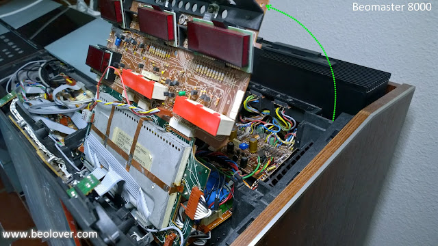
The display board and microcomputer boards are stacked together to form one assembly. The microcomputer board is the one on the bottom and is attached to a metal hinge that has a slot. The two board assembly can carefully be lifted up, pivoting on the hinge until the hinge catches in the slot. That will leave the microcomputer board and display board upright in the service position.
The right channel output amplifier board and power supply board are now visible.
That leaves the Filter & Tone Control panel to lift into service position so the left channel output amplifier, preamplifier, FM and FM Interface boards are accessible.
Those are the first steps in putting the Beomaster 8000 into a service position that allows the Beomaster to still function fully while a number of measurements and adjustments can be made.
In Part 2 of opening up the Beomaster components will be removed where the Beomaster will not remain intact and the receiver will no longer function.


No comments:
Post a Comment
Comments and suggestions are welcome!