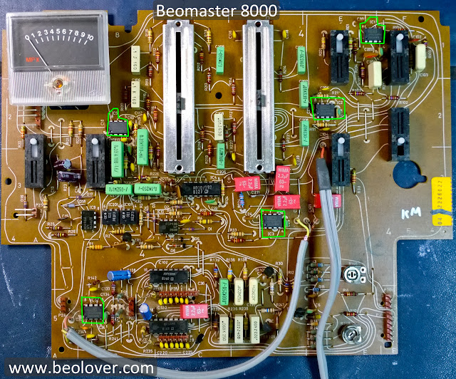
That problem turned out to be with the Analog Devices Digitally Controlled Audio Attenuator IC (AD7110). This was unfortunate as it is very hard to find this chip anymore. I had to pull two of these (one for the left channel and one for the right channel) from a spare Filter & Tone Control board. But then that is why we have spare boards.
Here is the circuit for the Beomaster 8000 volume control.
When I put the spare board next the the one I am working on I could immediately see a difference in the boards. The spare board was a later version of the board than the board from this Beomaster (serial number 2251030).
The older serial number Beomaster has extra components.
The Beomaster 8000 service manual has a section in the back that describes this circuit as a spike suppression circuit that was removed on later Beomasters.
Thank you B&O for providing good documentation.
After replacing the AD7110 chips the Beomaster volume control was working again. However, now I had some popping noises in the output when I switched the tone filter (bass & treble) on and off. I'm not talking about the slider controls which will need Deoxit treatment. The noise was happening when the Filter button was pressed.
At first I suspected the AD10/192 analog switch (also very difficult to find) so I swapped that IC with the one from my spare filter board but that didn't fix the problem. The filter circuitry uses three OpAmps that are either TL072 or LF343 type OpAmps. The Filter & Tone Control board has five of these in the signal path so I changed them out with OPA2134PA (TI) OpAmps. The OPA2134PA is a high quality audio OpAmp and is what I keep in stock for replacing older audio OpAmps.
That did the trick. No more noise in the Filter & Tone Control board. Here is a picture of the reworked board. The replaced OpAmps are outlined in the picture.
Just three more boards to go.


on my filter board it clearly shows that the negative on C111 is closest to the slider pots, and the negative on C211 is proximal (center of board). In these pics above and some others it's clearly opposite of what I see on the illustration on the back of my board. I did not check the polarity before i removed the old ones: I'm just now going be the ---|| |X|--- white indicator on back. Pics upon request. (where |X| is negative indicated by white solid rectangle)
ReplyDeleteI have to say that the schematic shows the polarity in the boards shown on this page, where Negative on C111 & C211 go to pins 7 & 1 (respectively) on IC3. But the white printed indicator on the back of the board shows the opposite :(
DeleteC111/211 are coupling capacitors in the signal path. Their polarity does not matter since they only see AC signals. Depending on the particular Beomaster, one can find them in both polarities. I guess, they had to specify a particular polarity on the diagrams since they used electrolytic capacitors.
Delete