Featured Post

Beolover SyncDrive: DC Platter Motor Replacement for Beogram 4002 and 4004 (Type 551x and 552x)

Late Beogram 4002 and the 4004 (Types 551x and 552x), which have DC platter motors instead of the earlier synchronous AC motors usually suff...

Saturday, May 27, 2023

Beogram 8000 Type 5513: Tomball Texas Project Electronic Work

The main electrical restoration work has been completed successfully on this Beogram 8000 from Tomball, Texas.

I changed out the old capacitors on PCB1 (including daughter boards PCB6 and PCB7), PCB2 and the Transformer Assembly.  I also changed out the microcomputer (uC) 40-pin socket in PCB2.

Here is the Beogram 8000 Transformer Assembly.
As named, it is the transformer for the Beogram but, for extra space savings, Bang & Olufsen used the Transformer Assembly box to house the 27uF, non-polar, electrolytic capacitor - C1 ...4C1 actually.


This old C1 capacitor measures 39uF instead of 27uF as shown on the capacitor...quite a bit out of tolerance.

I replaced it with two 56uF polarized capacitors in series to get close to 27uF and configured them so they will be non-polar.  That is with the two negative leads connected to each other.
I also mounted them in the transformer box using our Beolover 3D printed assembly.


The actual capacitance of this custom assembly measured 29uF so that is good.

I worked on the PCB2 assembly next.  That is the assembly that houses the micromputer (uC) IC.
Here is another photo of PCB2 before restoration.


As highlighted in the photo, capacitor C28 is the only electrolytic capacitor in this PCB.  It is part of the +5VDC supply voltage circuit for the uC.
One important note about replacing this capacitor is that the positive lead for the capacitor is soldered on the underside (trace side) of PCB2.  The negative side however, is soldered on both sides of PCB2.
Failure to solder the negative lead to ground on both sides of the board will cause the board to not work.

Here are some photos of the PCB2 restoration.


PCB2 and the Transformer Assembly are done.

Now on to PCB1 (and its related daughter PCBs: PCB6 and PCB7).

Here is the photo of PCB1 from my initial assessment post.


I didn't notice it at the time but once I started the restoration work on it I could see that capacitor 7C3 (of the Control for uC daughter-board) was completely blown.


That doesn't change anything regarding this restoration...it just confirms that these aging capacitors are often at the limit.

Here are some pictures of the other PCB1 capacitors prior to their replacement.


The next set of photos are after the capacitors were replaced.


For the +24 VDC power supply filter capacitor, 1C27, I like to remove the three-pronged base (which is the ground lead for 1C27) and re-use it on the replacement capacitor for 1C27.


Before continuing on and doing the restoration work on the floating chassis components and control panel, I decided that I couldn't wait for that to check out this electrical work so far.

I reassembled the PCB1 and PCB2 boards and checked them out on my Workshop Beogram 8000.
That is why I have that unit...it provides a nice tool to check out other Beogram 8000 boards.

The first power on is often an anxious moment but I was very confident these boards would work good.
While a majority of the original capacitors were out of tolerance, including that one, blown capacitor, this set of boards is in fantastic shape. The solder joints are all nice.  The board connectors are solid and great.  The ribbon cables plug into the connectors firmly and fit perfect.

Sure enough, plugging the Workbench Beogram 8000 in with this set of restored boards showed that they are working as they were designed.

Pressing Play, the Beogram searched the empty platter for a record, automatically switched from 33 RPM to 45 RPM at the correct position, then returned to Standby mode.


It always feels good after success like this.

The next steps will be to do all of the work on the floating chassis components and the control panel.
Once those are ready, I will connect those up with these completed boards and do a full functional test.
I will also measure voltages and check sensor signals at that point.

Monday, May 22, 2023

Beogram 4002 (5513): Installation of a Brand New Hood

There was one more item to address before the Beogram 4002 (5513) that I recently restored would be ready to return to its owner: The original hood already showed telltale signs of developing cracks around the area where the hinge bolts into it:


My customer decided to replace the hood a brand new reproduction hood from the Beoparts-shop in Denmark! These hoods are manufactured via injection moulding, exactly like the original hoods. This means there are no seams like you find them on previously available hoods made by fusing laser cut panels together. These hoods look exactly like the original ones!

This shows the new hood together with the appropriate 4002 reproduction aluminum trim:

For installation, the hinge needs to be removed from the old hood. To get to the bolts, the aluminum trim needs to be pried off from the sides. After removing the bolts the hinge comes off:
I used my alignment helpers to place the aluminum trim properly:
And this is the final result with the hinge bolted in, and the aluminum trim glued to the hood:

Beolovely! This Beogram 4002 is ready to go back to its owner!

Sunday, May 21, 2023

Beogram 4002 (5524): A New Arrival from Texas - A Wrong Hood and Some Blown Fuses

I recently received a Beogram 4002 (Type 5524) from Texas. The 5524 is a universal voltage 4002 DC motor version, i.e. carries the grid voltage switch on the bottom of the enclosure.

It arrived well-packaged in a Beolover-provided shipping container, and so no shipping damages occurred. This shows the unit as I received it:

If you are a B&O geek like myself, then looking at this picture will immediately tell you that there is something not quite right! The tint of the hood suggests 'Beogram 4000'! And indeed, a closer inspection of the aluminum trim on the hood revealed that this is actually a Beogram 4000 hood:

The later Beogram 4002/4 hoods are all grey tinted and not brownish like this one. I removed the hood, which was not bolted down and this revealed aluminum surfaces that are fairly decent. No mayor damages. Even the keypad is still pretty good, except a faint scrape in the upper center.

The plinth is also still pretty nice. The right corner has some minor damage at the bottom,
but the left corner is fairly pristine:
I removed the panels and platter. I immediately saw the large number of transport lock fragments distributed throughout the enclosure. Also, one of the hood bolt springs appeared lodged behind the left lock:
The other spring seems lost, but no problem: I have proper replacements for them. The overall impression at this point is that the deck is fairly original. No obvious 'creative' changes below deck:
I plugged the unit in, and pressed START. Nothing happened. Completely dead. I looked at the fuses and it showed that they both were burned out. In order to save fuses, I connected the deck directly to a bench power supply at the reservoir capacitor leads:
I slowly ramped the voltage up to 30V (make sure the negative lead is connected to the black wire and the positive to the white one if you try this at home) and the current stayed in the low 10s of mA range, indicating that they fuses must have blown during some 'intervention' where a short was caused.
This finally brought the deck to life. After pressing START the platter motor started rattling (indicative of dry bearings), and the arm moved to the LP setdown point where the solenoid tried (unsuccessfully) lowering the arm. So it seems the electronics are probably mostly o.k., and it has the usual hardened lubricants that prevent the arm lowering mechanism from actuating.
Now fairly confident that they would not burn out immediately, I put two 250mA slow-blow fuses into the fuses box,

plugged the deck in and then started it again. It worked exactly the same as when powered by the bench supply. 

In summary, it seems that this 4002 project should be fairly straight forward. Stay tuned for the restoration report.

Thursday, May 4, 2023

Beogram 8000 Type 5613: Tomball Texas project restoration

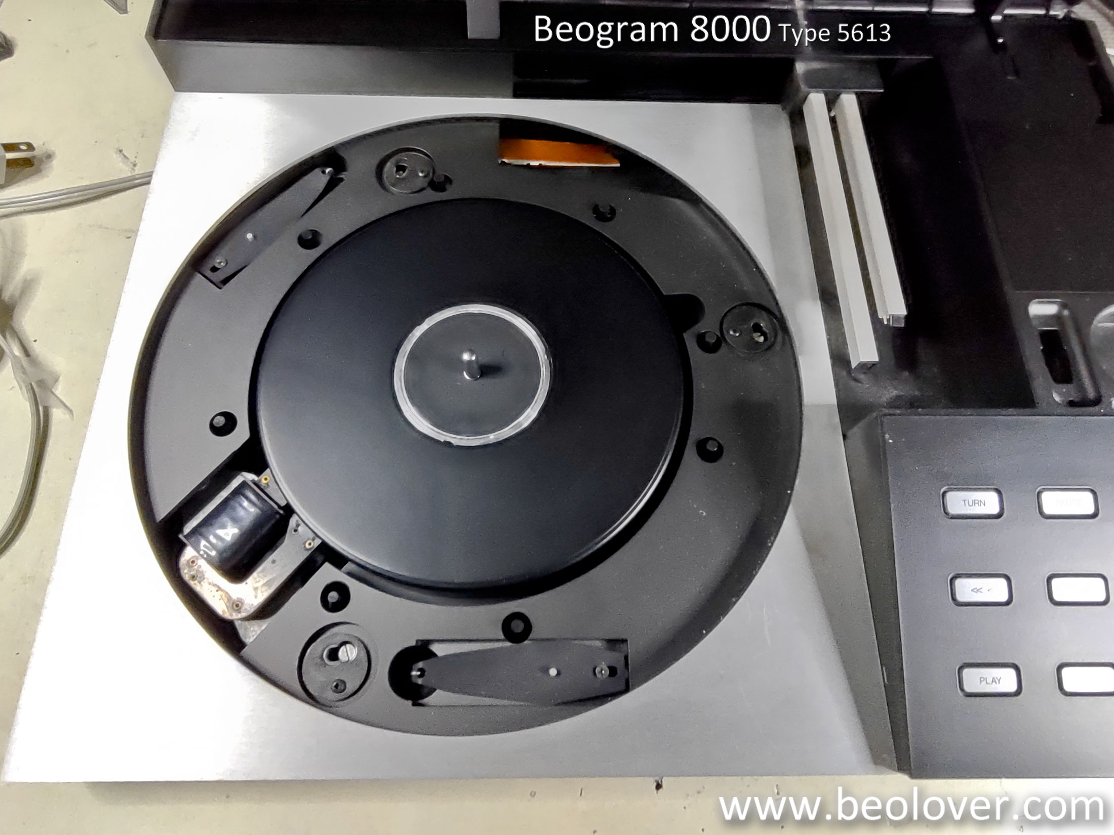
This post shows the initial assessment of a nice, original owner's Beogram 8000 turntable sent to me for restoration.  Since the owner was in the same state we arranged for person to person pickup instead of dealing with packing and shipping.  I like that a lot better when the worry about shipping is out of the picture.

This Beogram 8000 is in great shape cosmetically.  The problems with it are the usual problems with aging parts in the Beogram.  It is over forty years old and without any restoration work, these turntables usually are no longer working at this point.


I proceeded with disassembling the Beogram 8000 by unlocking the floating chassis and removing trim panels.  

This Beogram 8000 has already had the metal deck plate and access door (over the tonearm) re-attached. The dust cover works great and the lowering hinge appears to be in good shape. 


There is a lot of dust debris scattered around in the cabinet.
Removing the black, metal lid under the tonearm revealed why.


The original B&O double-sided tape for that lid assembly has deteriorated and produced dust particles everywhere around it.

That isn't unexpected and will clean up pretty easy.  I will reattach the separated pieces with 3M VHB double-sided tape.

Next, I opened and removed the control panel assembly.


An important and nice thing here is that all of the plastic mounting tabs that attach the control panel PCB to the button panel are all intact.  Those tabs are often broken off by people attempting to open the button panel incorrectly.  This one is perfect.


To get to the main turntable components for assessment and removal I had to put the Beogram 8000 into its service position.  That means removing two screws on the left, underside of the cabinet (not shown in the photo) and disconnecting the three floating chassis spring clips (as shown).


With some careful maneuvering of some Beogram parts to avoid the deck from hitting the arm assembly, I lifted up the cabinet lid to reveal the floating chassis underneath.


I don't like to leave the Beogram 8000 in this service position because there is nothing to hold the tilted cabinet top in this position.  I am sure a good number of dust covers have been damaged because of incidents involving service position mishaps.

My technique is to temporarily secure the cabinet while I remove all of the internal components.
After that, I close the cabinet back up and store it safely away while I work on the internal component restorations.

Here are the Beogram 8000 internal components removed.


I was happy to see that this serial number Beogram 8000 has all of the circuit modifications B&O added to the Beogram 8000.


Earlier serial number Beogram 8000 turntables don't have all of the add-on boards shown (outlined) in the photo.  

Everything on the boards is original as I would expect.

This Beogram does have the earlier model platter speed sensor though.  That isn't a problem but is important to note because the current limiting resistors for the speed sensor are located on the main PCB and not on the speed sensor assembly as later Beogram 800x turntables have.

Here is the speed sensor and the current limiting resistors (on the main PCB).


This Beogram does have the early, plastic type tachodisc that the speed sensor reads for speed information.  The disc is in decent shape but I recommend that it be replaced with the later type B&O tachodisc which is a metal disc.


The inside of the transformer assembly looks good.
I will replace the bipolar capacitor with a new one as part of the restoration.


On the microcomputer (uC) assembly, I will replace the C28 capacitor there and will install a new, modern socket for the uC IC.


On the floating chassis there are two capacitors that will need replacing.  They are on a voltage regulator.


Another floating chassis component that will be replaced isn't in the photos and is the phono muting relay that is attached to the small PCB with the DIN phono socket.

The last few things I like to look at during a Beogram 8000 assessment is the tangential arm assembly and its spindle.


Everything looks good. Of course I will be cleaning off the old grease and oil to redo those mechanical items.  I cleaned some grease off the white, plastic nut on the spindle.  That is a part I always check first.  This one is in great shape but occasionally I will come across a Beogram 8000 where that spindle nut is damaged and has to be replaced.  So I always check that at the start.

Aside from replacing the electrolytic capacitors in this Beogram I will reflow the solder joints of all the board connectors. The mechanical parts will be cleaned and relubricated.  It is a usual retoration step to replace the servo motor belt with a new one so I will check that. A new, metal tachodisc will be installed. The service manual checks and adjustments will be performed.  During those tests I will measure and look at all of the sensor signals on an oscilloscope to verify everything is good.