I finished up the previous post on this Beocord 5000 thinking that I would do some quick recordings and then wrap up this cassette deck project.
While this Beocord did record and playback test signals well I don't really have a proper set of calibration cassettes to test the frequency response. The Beocord 5000 service manual doesn't call out a frequency response test but it does contain a whole section of electrical adjustment procedures.
That being the case I decided that it was necessary to go through those with this cassette deck.
The adjustment procedures for a cassette deck are very time consuming compared to a Beogram turntable or a Beomaster amplifier. Especially two-head tape decks. With a three-head machine you can measure what is being recorded as you are taping. On a two-head machine there are a lot of iterations where a recording is made, then a rewind and play of the tape to measure the result of the recording. After that, adjustments are made and the recording, rewind and play is repeated...until the desired result is reached.
So let's begin the fun :-).
Actually, I am not going to document all of the measurement iterations here.
Instead, I will go through the electrical adjustments, show photos of the relevant measurement points and list the procedures I performed.
The Beocord 5000 Type 4923 service manual does explain things pretty well and has good diagrams. There are a few places where the instructions could have been a bit more verbose.
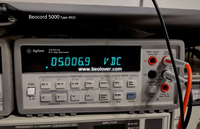
The first electrical adjustment called out in the Beocord 5000 service manual is for the reference +5 VDC.
With the Beocord stopped and its tape counter cleared the +5 VDC power supply is monitored at a test point on one side of resistor 1R55. The DMM probe is place on the +5 VDC side of the resistor and measured to ground. The adjustment is done using trimmer 3R24 on the Beocord 5000 power supply board.


Next is the azimuth adjustment. The tape head has a screw that the service manual labels as "A". That screw adjusts the tape head azimuth.
The procedure begins with making sure the tape heads are cleaned and demagnetized.
I use a Nakamichi DM-10 hand-held demagnetizer.
After the cassette mechanism is prepared a special calibration tape with a 12.5 KHz test tone is played on the Beocord. The left and right audio signals of the Beocord are measured at 1TP3 and 1TP4 test points. Tape head screw "A" is adjusted while the calibration tape plays so that the left and right channel signals are in phase.
I use an oscilloscope to monitor 1TP3 and 1TP4 during this adjustment.
You can see that the azimuth adjustment screw can make the two channels in and out of phase.
The objective here is for as good signals as possible on both channels that are in phase.
After the azimuth test is the
tape speed test that includes the WOW and Flutter test plus the Drift test.
That is another test that requires a special calibration cassette.
In this case a DIN 3.15 KHz test signal plays at 1 7/8 ips.
The procedure uses a WOW and Flutter meter with a Drift meter to adjust the Beocord capstan motor speed. I use a Leader LFM-39A WOW & Flutter meter set to the 0.3 scale.
The measurement is performed in W&F mode and the DIN 3.15KHz button on.
The drift is set to the minimum possible setting by adjusting the Beocord motor speed.
The WOW & Flutter is measured and checked to see if it is less than ±0.13%.
The speed deviation (drift) should be less than ±1.5%.
This Beocord had a speed deviation of approximately 0.2% and a WOW & Flutter measurement of 0.06%.
Playback level adjustment is the next test.
There are actually two checks in this procedure.
Both require special calibration cassettes.
The first playback level test uses a DIN standard 315 Hz, 250nWb/m tape.
The tape playback is monitored for left and right channels using 2TP5 (R-CH) and 2TP6 (L-CH).
Trimmers 1R217 (R-CH) and 1R417 (L-CH) are adjusted to get 660 millivolts at the test points.
The two trimmers are shown in the right pane of the following photo.
Using the same test points and adjustment trimmers the test is run again with a different calibration tape.
This time the calibration tape used is Dolby Level 400 Hz, 200 nWb/m test tape.
The test points are checked this time for 580 millivolts on each channel.
We are about a third of the way through the adjustment procedures now.
A number of the procedures coming up next call for a specific cassette type.
The Beocord 5000 detects and has settings for three cassette types: Fe (Type I), Cr (Type II) and MP (Type IV).
Here are the three different types that I use for these adjustment procedures.
The rear edges of the cassette cases have standard slots and tabs the audio industry defined for equipment to automatically detect the type of tape.
This picture shows the ends of the cassette cases for the three different types of tape.
On the Beocord 5000 these are the tape detection switches.
The Beocord 5000 service manual covers tape bias adjustments for all three types of tape so they must be loaded accordingly for the procedures they correspond two. As you can see the physical cassette case controls circuit selection in the Beocord via the cassette mode switches.
The baseline type of tape for the Beocord 5000 is Cr (Type II).
The service manual uses the Cr tape type selection settings first in the record boost, record current and bias adjustments. After those adjustments are made the service manual adjusts for Fe (Type I) and then finishes with MP (Type IV).
The next procedure in the service manual electrical adjustments is for
record boost.
A Cr (Type II) tape is loaded. A test bench tone generator is used to provide a test signal (sine wave) of 333 Hz and 30 millivolts.
Test points 1TP7 and 1TP8 are monitored with a DMM.
The Beocord is put into Record Open and Record mode (but not actually recording).
The record potentiometers are adjusted so the measurements at 1TP7 (R-CH) and 1TP8 (L-CH) measure 100 millivolts.
Test points 1TP3 (R-CH) and 1TP4 (L-CH) are then measured (and noted).
The test signal generated is changed from outputting a 333 Hz signal to outputting a 19 KHz signal.
The test signal amplitude stays the same (30 millivolts).
The Beocord test points at 1TP3 and 1TP4 are measured again.
If they are not the same as the values measured for 333 Hz the record potentiometers should be used to adjust them so that the values here at 19 KHz match the values measured at 333 Hz.
Once those values match the DMM probes are moved back to measure 1TP7 (R-CH) and 1TP8 (L-CH).
The two Record Boost variable inductors: 1L201 (R-CH) and 1L401 (L-CH) are adjusted so their corresponding test points measure 1.4 volts.
The service manual notes that this adjustment corresponds to a +23 dB difference at 19 KHz in relation to 333 Hz.
The recording LED display (PPM) adjustment is the next adjustment.
Here are the PPM displays on the Beocord 5000.
The
PPM adjustment calibrates the setting of those record meter LEDs.
The service manual lists two adjustment procedures but the second procedure is only if parts involved with the PPM have been replaced.
That is not the case here so I am only doing the first procedure.
The first procedure uses a bench signal generator again to provide a 333 Hz sine wave signal.
This time the amplitude is 300 millivolts.
The test points at 2TP5 (R-CH) and 2TP6 (L-CH) are used to make the measurements this time.
Note: These same two test points will be used later for the Dolby Filter adjustment as well.
The Beocord 5000 is put into the Record (paused) mode again.
The record potentiometers are adjusted to measure 660 millivolts at the test points for the two channels (2TP5 and 2TP6).
With those values adjusted to, trimmer 1R133 is adjusted so the first red LED in the PPM is just beginning to glow.
This photo shows the location of the 1R133 trimmer.
Note: The probe at 1TP12 in the photo is not part of the PPM adjustment procedure.
With the probes still attached to the 2TP5 (R-CH) and 2TP6 (L-CH) test points the service manual proceeds to the
Dolby filter adjustment.
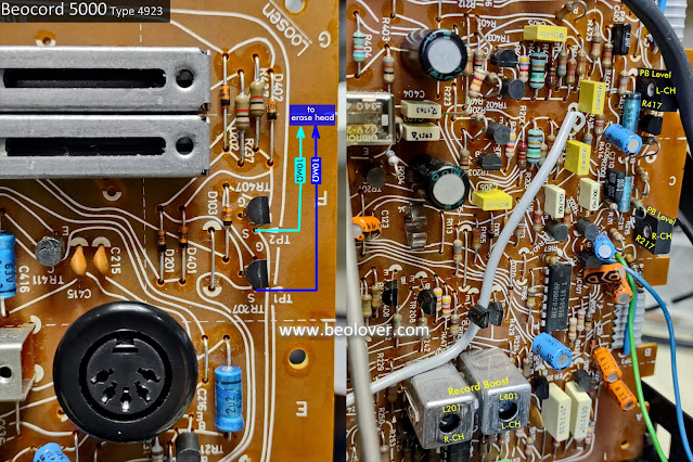
For this test the service manual calls for temporarily installing 10 MΩ resistors between 1TP1 (R-CH) and 1TP2 (L-CH) to the tape head (the side not connected to ground).
I used minigrabber probes and test leads to connect the test resistors in place.
For this adjustment 2TP5 and 2TP6 are monitored.
The Beocord is put in Record (paused) mode again.
The record potentiometers are placed in the center position.
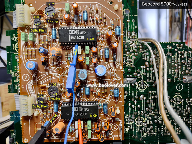
Dolby Filter variable inductors 2L101 and 2L201 are adjusted to get the minimum voltage readings at their respective test points.
The next Dolby related test is the
Skewing test.
For this adjustment the Dolby switch is put in the Dolby C position.
A bench signal generator is setup to provide a 19.9 KHz (±200 Hz) sine wave signal at an amplitude of 300 millivolts.
The Beocord is put into the Record (paused) mode once again.
The record potentiometers are set so the test points at 2TP5 and 2TP6 measure 300 millivolts.
The two variable inductors for the Dolby Skewing adjustment are used to get minimum deflection at 2TP5 and 2TP6.
We are now two-thirds of the way through the service manual electrical adjustments.
Bias and Recording current adjustments are next.
The service manual doesn't state any Dolby selection settings so I am taking that to mean the Dolby switch is back to the off position.
The service manual calls for beginning the bias and recording current procedure with Cr bias (L-CH and R-CH) trimmers 3/4 turn to the right of center and the Rec. Current trimmers at their center position.
That is to just give a common starting point.
These adjustments will require numerous iterations of recording and playback to make the proper adjustments. The starting positions for the trimmers is to hopefully be close to where the final settings will be.
Here is a picture of all the adjustment points for the recording current and biasing.
The procedures start off with the variable inductors for the bias amplifier and bias filter.
1L202, 1L402, 1L203 and 1L403.
Test points 1TP9 (R-CH) and 1TP10 (L-CH) are measured with respect to -15 VDC (instead of ground).
The variable inductors are adjusted so the DC voltage measurements at the test points are at their minimum possible deflection.
Once the Bias Amplifier and Bias Filter inductors are set the Recording Current adjustment can begin.
The Recording Current and bias adjustment procedures all involve applying a known test signal from a signal generator, making a recording onto a test tape and checking the level of the recording.
The objective is to get the recorded signal playing back at a desired amplitude per the service manual.
For the Recording Current adjustment a Cr (Type II) cassette is inserted for the recording and playback testing.

A bench signal generator is set to provide a 333 Hz, 300 millivolt sine test signal.
The Beocord is put into the Record (paused) mode and the record potentiometers are adjusted so test points 2TP5 (R-CH) and 2TP6 (L-CH) measure 200 millivolts.
The Beocord is then allowed to record the test signal for however length of time the tester would like to record for. I generally record about 20 seconds before rewinding and playing back the recorded signal.
When playing back the recorded signal the two test points (2TP5 and 2TP6) are expected to measure the same level the recording was set to: 200 millivolts.
If that playback level is not 200 millivolts then trimmers 1R270 (R-CH) and 1R470 (L-CH) are used to adjust the recording level.
IMPORTANT NOTE: The 1R270 and 1R470 adjustment results will not be known until another test recording is made and the playback measured on test points 2TP5 and 2TP6 again.
You can see now how fine tuning this adjustment can take a few iterations.
In the future I think that I would rather switch the Beocord 5000 adjustment trimmers to sealed multi-turn type trimmers.
Once the procedure results in 200 millivolts, 333 Hz playback signals for both channels I could move to the next procedure, the Cr (Type II) tape bias adjustment.
The Cr (Type II) bias procedure is similar in steps to the Recording Current adjustment in that a recording is made and the playback checked until the desired result is achieved.
For this test a signal generated sine wave of 333 Hz, 30 millivolts is used.
The same test points, 2TP5 and 2TP6 are used for the measurements.
The objective here is to set the recording level for the 333 Hz, 30 millivolts test signal at 20 millivolts using the record potentiometers (as measured at 2TP5 and 2TP6).
A recording of that signal should produce a playback signal also at 20 millivolts (333 Hz). That is because of the previous Recording Current calibration.
Now, for completion of the Cr (Type II) bias adjustment the objective is to change the recording test signal from 333 Hz to 15 KHz. All other settings are to remain the same.
The 15 KHz signal is to be recorded and the playback checked to see if it matches the 20 millivolts amplitude that was measured for the 333 Hz test signal.
If the playback result is not 20 millivolts the Cr Bias trimmers are used to make the adjustment.
Just like before...and adjustment is made to the trimmers then another recording is made and tested.
That iteration continues until the playback signal amplitude at 15 KHz matches the amplitude at 333 Hz.
If you are still with me that completes the Cr (Type II) bias adjustment.
Now the test tape is changed to Fe (Type I) type tape for that bias adjustment.

For the Fe (Type I) and the MP (Type IV) bias adjustments there is only one bias trim pot for each.
The Cr (Type II) type tape had two trimmers (one for the left channel and one for the right channel).
That simplifies the procedure a tiny bit. Although I still measure both channels when comparing the playback levels.
The adjustment procedure is primarily a repeat of the Cr (Type II) bias adjustment procedure.
The test signal is a 333 Hz sine wave again. The amplitude and record potentiometer settings should be the same as from the previous, Cr bias test.
The recording on the Fe tape is made at 333 Hz first. The playback is then checked and should be pretty much still on 20 millivolts.
After confirming that, the test signal is changed to 15 KHz and another recording made.
If the playback of that signal is not 20 millivolts then the 15 KHz recording/playback test is performed again after whatever adjustment was tried using trimmer 1R159 (Fe bias trimmer).
Once the playback amplitude at 15 KHz matches the amplitude at 333 Hz the Fe bias adjustment is complete.
The final bias adjustment is for metal type cassette tape: MP (Type IV).

This procedure is a duplicate of the Fe (Type I) bias adjustment steps.
The main difference is that in leaving the test setup the same from the previous bias adjustment procedures (Cr and Fe), the starting recording and playback measurement for the 333 Hz test signal will most likely yield a playback amplitude less that the 20 millivolts measured using the other two tape types.
In my test I measured between 16 millivolts and 17 millivolts for the 333 Hz recording and playback on the MP type tape.
That is okay.
The objective of this MP bias procedure then is to adjust the MP bias trimmer, 1R162, such that I also get 16 millivolts to 17 millivolts on the 15 KHz test signal recording...and I was able to achieve that.
The final service manual electrical adjustment is a little strange.
It is the Advance adjustment procedure.
I believe it is adjusted and working correctly but this procedure is the one adjustment that made me scratch my head.
The bench signal generator is used again.
Initially it is setup for 333 Hz and 300 millivolts again.
The Cr (Type II) test tape is used again.
With the Beocord 5000 put into Record (paused) mode the record potentiometers are adjusted until the first PPM LED starts to glow.
I interpret that to mean the very first, green LED at the start of the PPM scale.
Once that is set the test signal is lowered by 30 dB. That puts it at about 9.5 millivolts.
The test signal frequency is changed from 333 Hz to 2.5 KHz.
The Beocord 5000 record button is started and a recording is made.
I let the recording go for about 20 to 30 seconds then stopped and returned to the beginning of the recording.
The adjustment procedure says to playback the recording while measuring the signal on an oscilloscope in DC mode at test point 1TP12.
The service manual says the trimmer 1R182 can be adjusted so that the measured value on the oscilloscope (at 1TP12) alternates between 0 and 12 volts.
During playback of the test recording (9.5 millivolts, 2.5 KHz) I don't see any result in adjusting 1R182 (Advance trimmer).
I do see that the Beocord "Return" function works and when the tape returns to the start of the recording for play the measurement at 1TP12 goes to 0 V and before that it is at 12.6 V.
So on this Advance procedure I feel a little more investigation and learning is in order.
For now, this wraps up this round of Beocord 5000 service manual adjustments and I will move on to testing actual music recordings on the Beocord using the Beomaster 5000 it came with.