Featured Post

Beolover SyncDrive: DC Platter Motor Replacement for Beogram 4002 and 4004 (Type 551x and 552x)

Late Beogram 4002 and the 4004 (Types 551x and 552x), which have DC platter motors instead of the earlier synchronous AC motors usually suff...

Sunday, August 12, 2018

Canada Beomaster 8000: Removing the output amplifier boards

The Beomaster 8000 has two identical output amplifier assemblies (a circuit board plus a heatsink with transistors). When I replace the electrolytic capacitors and the trimmer resistors on these boards I like to remove the output amplifier assemblies from the Beomaster completely. It is possible to recap the board by leaving it in the Beomaster and tilting the board up but I feel like I do a better job when I can deal with the board by itself. Plus I can test the output amplifier on my workbench outside of the Beomaster.

Removing the output amplifier boards doesn't sound too difficult. The Beomaster 8000 service manual says that you just removed the heatsink mounting screws and the little speaker panel. After that you rotate the circuit board ninety degrees and pull it out through the rectangular opening in the back of the Beomaster cabinet frame.

So let's try that.

Here is the back of the Beomaster 8000.


The rear cover plate has eight screws connecting it to the two amplifier heat sinks. Removing those eight screws allow the metal cabinet cover to be lifted off and expose the heatsink assemblies.


The left and right sides of the cabinet each have a screw holding the speaker terminal plate to the cabinet frame.


The back of the cabinet center plate then has four remaining screws that are attached to the two heatsink assemblies. Both heatsink assemblies have two screws that connect them to their cabinet mounting brackets. All of those screws must be removed. Here is the left channel heatsink with the screws removed.


The heatsink assembly can now be pulled away from its mounting brackets exposing the rectangular opening in the cabinet frame that the service manual refers to.  This left channel is particularly tight due to the small ledge inside the cabinet for the lid damping assembly.


You can see in the above photo that there is a nice size cable bundle under the lid damper shelf that makes the board removal tricky. The photo also shows six connectors at the rear of the board that must be removed.  Those are the ±55 VDC and ground inputs to the board along with the output amplifier outputs.

Here are those connectors disconnected.


It is starting to look like there is more room now to possibly get the board out through the back of the Beomaster. The next step is to rotate the board ninety degrees. There should be just enough slack in the cables from the board to the heatsink mounted components to perform the maneuver.


The left channel output amplifier is oriented properly for exit from cabinet now. There is still an obstruction from the large cable that goes underneath the damper lid ledge.


To provide some slack in the obstructing cable the left channel reservoir capacitors need to be lifted.
Doing that allows that cable to be moved towards the front of the damper lid ledge and providing just enough space for the output amplifier board to finally slide out.


There...it is out.

Not quite as easy as it sounds. In fact this is only the second time I have done it this way. In previous Beomaster 8000 project posts I remove the retaining clips for the heatsink mounted components and pull them through the opening to remove the output amplifier board from the inside of the Beomaster cabinet.

That technique works well for removing the boards especially since the heatsink mounted components are going to be checked anyway and new thermal protection installed.

Re-installing the boards after the restoration is a different story. Once the boards are recapped and tested out on the bench I will want to get them back into the Beomaster cabinet. It would be nice to be able to install them with the heatsink mounted components installed. That is why learning tricks to using the service manual method of removal is a valuable technique to master.

The right channel output amplifier is a little bit easier to manage but it is still pretty tight and there isn't much operating room. However, there isn't an obstructive ledge and it is easier to move the other cables out of the way.


Definitely more room here.


The right channel output board easily rotated ninety degrees and out it came.


Here are the Beomaster 8000 output amplifier boards ready for restoration and then bench testing.


While these boards are out I will start the recap work on the Beomaster power supply board and reservoir capacitors.

Wednesday, August 8, 2018

Beomaster 8000: New Project From Texas

The second Beomaster 8000 project I have to start on is from right here in Texas. It is nice to not have to deal with shipping these heavy Beomaster receivers.

The owner of this Beomaster has owned this receiver for a long time and used it regularly until it stopped working on him.  Time to open it up and see what the condition of this unit is.


It looks good on the outside.

Under the filter and tone control lid the source input panel is showing signs of corrosion bubbles.


Here is the Beomaster 8000 opened up in the service position.


The parts look original. That is good but this unit is in need of a recapping of the electrolytic capacitors for sure.

I found some other mechanical problems on this Beomaster.

The phono DIN jack has a glue repair. We have seen this type of repair before. The original panel mount for the DIN jack breaks and people try to use epoxy to build a replacement. That makes a messy substitute but can work in a pinch. Fortunately Beolover makes a 3-D printed replacement part for this problem now.


The other mechanical problem is the filter and tone control panel lid has a broken lever. A repair attempt was also made on this problem but wasn't successful.


Beolover makes a 3-D printed replacement part for the lever. I will see if the damper can still be used but I do have a spare if it can't. Quite a few of these levers are broken and I think it is caused by repair persons not understanding how to remove them. Also, the lever part that connects to the damper does not snap on and off. It has a keyed opening that slides onto a post on the damper.

Another common Beomaster 8000 problem are the two ribbon cables that attach to the control panel. These have started to separate from the panel board.


A repair attempt was made with some tape but that won't do the trick. I will test those connections and re-attach the cables during the restoration. If the cables are not good I can use some reproduction cables from Beolover.

The left channel and right channel output amplifier boards use the same Bang & Olufsen parts. Both boards are original but in need of restoration. As you can see by the darkened areas of the boards they have been exposed to a lot of heat.


The power supply board also shows some dark areas from heat.


Apart from the mechanical damage this Beomaster is pretty typical of other Beomaster 8000 units I have seen. I don't see anything that would prevent restoring this unit to like new condition again.


Beomaster 8000: A New Project From Canada

Today I started looking at two new Beomaster 8000 restoration projects.  This seems to be the year for Bang & Olufsen owners ("Beolovers") to begin the process of getting their Beosystem 8000 audio gear back into good working order.

This first Beomaster 8000 is from Canada and looks to be in very good condition. The owner is not the original owner of this fine receiver but has requested our usual restoration and I look forward to making it like new again.


One question an owner wants to know is if the unit is in its original condition. Let's take a look.

The display board has a couple of breaks in the board where it attaches with screws to the cabinet.
Those don't look bad and can be repaired.


There are a couple of electrolytic capacitors here and there that have been replaced before but I would say most of the components inside this Beomaster are the original parts.


The output amplifier boards are in really good physical shape. They don't have the usual scorch marks from heat.


The control panel lid has its lid damper and lever mechanisms intact.


The source input panel is still in good shape.


This is good news for this project. It doesn't look there will need to be any mechanical repairs.

Monday, August 6, 2018

Beomaster 4400 (2419): 30 Hour 60dB Test

Functional testing update...
Because of the earlier incident with the left channel 5R173 and 5R174 resistor failures I am putting this Beomaster through extra long burn-in testing.

Over the weekend this receiver successfully played continuously for thirty hours at a volume level that produced 60dB to 65dB of sound out of my Beovox S55 speakers (measured from 15 feet away).
The output transistors on the heat sinks measured around 100°F to 120°F at various times during the thirty hour test.


The testing continues.

Friday, August 3, 2018

Beomaster 4400 (2419): Preparing for Functional Tests

The Beomaster 4400 has been powering on and off without any problems since the 5R173 and 5R174 incident from the last post. I am satisfied it is ready to move on to functional testing and the long burn-in tests.

I re-assembled the bottom part of the cabinet and re-attached the slider control bar. While it was removed I cleaned off the old grease and applied new, clean grease for the slide controls.

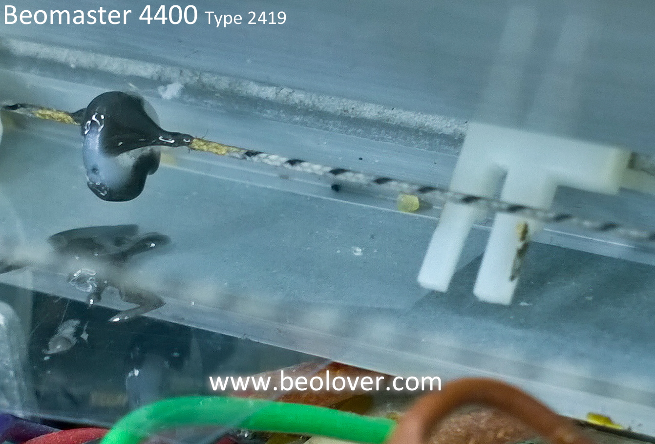
In lining up the slider control slots with their catches I saw that the tuning cord catch for the tuning dial had started to fall apart. The main plastic post was mostly missing. It looked like the catch was mostly hardened glue.


That left over clump of glue wasn't going to fly. In fact more pieces of it started to crumble when I touched it. I needed to fashion a substitute.

After looking through my parts bins and thinking about it I decided a nylon, M2 washer could become the new tuning cord catch. I cut a small section out of the washer so it would fit over the tuning cord. I marked either side of the old, remaining catch then carefully removed the old piece.
I used Araldite fast setting epoxy to attach the washer to the tuning cord.


After test fitting that with the tuning dial slot I added some JB Weld fast setting epoxy in the washer slot that I had cut and along the top of the tuning cord and the washer. That secures the washer better and provides a little mounting edge to fit in the tuning dial slot. One reason to use JB Weld for that last part shaping was because the color difference helped be tell the glue was where I wanted it.


I let the epoxy cure then tried out the new catch. It fits great and looks like it will work well.


Before I put the top cover on I will do some functional testing with the reassembly I have done so far.  Now for a little relaxation and test listening of the Beomaster.


Wednesday, August 1, 2018

Beomaster 4400 (2419): Amplifier Frequency Response Check Plus A Fault Detour

In the last post I showed the results of some THD tests with the Beomaster 4400.  I used a 1KHz, 2Vp-p sine wave input signal at Tape 1 and Tape 2. Then I used the QuantAsylum QA400 analyzer to measure and display the output signal across 8Ω dummy speaker loads.  I also ran the volume of the Beomaster up to its maximum output right before the overload lamp illuminates. The Beomaster passed those performance tests really well.

After letting the Beomaster sit for a couple of days while I took care of some other things I powered it back up for some frequency response testing.  To my horror and surprise the left channel output amplifier had smoke!  I quickly unplugged the Beomaster and examined the damage. The smoke came from the main board 5R173 and 5R174 resistors.  They are 68Ω 1/8W metal film resistors and completely failed where they were open circuit now. Surprisingly there was not burnt areas of the circuit board and no other components appeared to be damaged. Quite puzzling considering the Beomaster had just come off almost 30 hours of testing.  Twenty-four hours of that was continuous playing of music on the Beovox S-55 speakers.

The next step was to try and figure out if there were other damaged components and how many.

Here is the related circuit. It is the left channel output amplifier circuit and shows that the two 68Ω resistors connect to the -35VDC rail. They get current when 5TR119 turns on. Too much current had to of gone through both R173 and R174 to cause them to burn up.


Here are the two burned resistors.


Here is the PC5 board - fault area. The photo shows the D103 12V zener removed for testing.


I removed related components to R173 and R174 as well as some other components that were in close proximity to test if anything else was damaged.

The D103 12V zener diode was a suspect because it controls TR119 which must of allowed too much current down through the two 68Ω, 1/8W resistors.

D103 was placed on a breadboard with a 1KΩ resistor to check if the zener still works. Using a bench power supply I applied 30VDC across D103 and the load resistor.  The zener held at around 12.5VDC.  I tried this several times and D103 appeared to be fine.

I couldn't find any components that tested faulty so I re-installed everything I removed.


Next I used my variac to slowly apply AC power to the Beomaster while watching R173 and R174.  I reached 120VAC on the variac without incident.

At this point I have to figure there was some problem on the board. Most likely a bad solder joint. Uninstalling and reinstalling the components around the fault area forced a re-flow of the solder joints.

I powered the Beomaster off and on several times and it appeared to be back to normal.

A little history on this Beomaster unit...
The owner told me when I started on the restoration that he had smelled burning in the receiver before but that it went away. After a period of time though, there was a loud squawk in one of the channels and the Beomaster stopped functioning. The Beomaster was taken out of service and eventually sent to me.

When I opened the Beomaster for restoration one of the inspections I did was to look for burnt components. I didn't find any. I thought the recapping work took care of any bad component behavior and solder joint problems. Then this fault occurred...even after the lengthy initial burn-in testing.

So I still worry there might be a weak component that is really the culprit. That means I will have to put this Beomaster through a much longer burn-in test period once I wrap up the frequency response and functional tests.

Continuing on with the frequency response measurements....
Like the 1KHz THD tests I used the Beomaster tape inputs to apply the QA400 frequency response impulse stimulus. The QA400 inputs were connected to the 8Ω dummy speaker loads through a QA190 differential voltage probe. The frequency response measurement function of the QA400 was then used to measure the response curve.

My initial frequency response measurements were okay, not great. Even with the differential probe measuring one channel at a time I get some noise that makes taking the measurements I would like a little difficult.

Here are the first set of frequency response curves I measured.


Both channels roll off a little steeper than I would like and the right channel is not flat at all.

The Beomaster 4400 Linear switch allows you to bypass the tone control circuit so I tried the measurements with the switch engaged.


That is a definite improvement versus going through the tone control circuit.
I cleaned the bass, treble and balance slider pots as well as the high and low filter switches to see if that helped the tone control path.


It looks like the right channel improved with a flat curve between 100Hz and 3KHz now.  My probe isn't doing a good job below 100Hz however so I am not able to get an accurate assessment of that part of the response.

Soundwise this Beomaster sounds good to me so I will keep these measurements filed as a reference for the next Beomaster 4400 units I have in my backlog.

The next steps for this Beomaster are to check out the phono input and the tape record paths of Tape 1 and Tape 2.  Once those have been tested I will hook this Beomaster to some audio components in a listening room for an extended burn-in test. If the R173 and R174 over current problem is still there it should expose itself during that period.