Featured Post

Beolover SyncDrive: DC Platter Motor Replacement for Beogram 4002 and 4004 (Type 551x and 552x)

Late Beogram 4002 and the 4004 (Types 551x and 552x), which have DC platter motors instead of the earlier synchronous AC motors usually suff...

Saturday, March 15, 2014

Beomaster 6000 Quad: First Contact

I finally found a Beomaster 6000 4-Channel (2702 Model) on ebay. The usual seller description implied not working and 'have not the right cables to test'...very 'funny'. This usually means someone messed with it and was not able to get it to work. In this case my B&O addiction in combination with the rarity of this model in the US won and I put a high bid in. The exterior is not too bad, but there are a few scuffs on the metal panels and especially on the frequency dial, as well as on the plexiglass cover. Well, I figured, better learn to work on one that is not so perfect, and then get a perfect one to serve as "beolover's masterpiece"...;-). So here we go: This is how it looked out of the box:


There is not much information about the technical aspects of this Beomaster out there except an excellent thread on Beoword.org by Geoff, who heroically fixed one up and let the world know how it went. Reading this post a couple years ago immediately made want one of these beasts, and try to cut my teeth on it...;-). His issues with the output transistors suggested not to turn the Beomaster on before having had a good look inside. Here is how I opened it up:
I followed the advice on the bottom:


I removed the bolts marked B (and A...not sure why they labeled them differently, they need to come off to be able to remove the wood trim). Here we go:


The bolts have two functions: To hold the trim to the enclosure, and hold the enclosure together. this means, that at this point, the top parts of the enclosure are loose, and one needs to hold the housing together when turning the Beomaster around after this step.
The final thing to do is to remove the nut that secures the frequency dial shaft in its bearings. I was a bit confused about this. Geoff sent me some advice (thank you very much!) and I forged ahead. This shows the nut in detail:


I used flat nose pliers to turn the nut while holding the dial on the other side against the turning motion. The nut came off easily, but then I was in trouble:
The dial came out and I slowly lowered it from underneath the housing (the Beomaster was hanging over the edge of my work bench for this procedure, so I could turn the nut from above and get the dial out from below). Unfortunately, the pulley that advances the string that moves the frequency indicator tape also emerged. Here is a picture:


The pulley is the brass part, and I think it is supposed to stay on the bearing as shown here as part 158 in the service manual:


Now I turned the Beomaster around, and removed the top parts, i.e. the control panel, the plexiglass cover, and the heatsink cover (after removing the four screws on the back and the two hex (2mm head) screws that hold it near the push buttons). The control panel cover is permanently attached by wires, but can be flipped out towards the front. This shows the state of affairs after removing the panels:


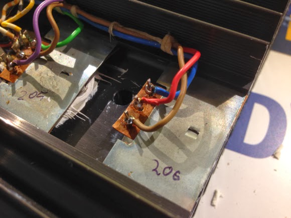
This is a close up of the frequency dial area where the pulley came out:


It is obvious that this is not how it should be where the pulley is clearly still seated in the bearing (the part in the center of the picture between purple capacitor pulley and capacitor to the right). Geoff sent me this pic from his Beomaster 6000:


Obviously his pulley is in place and actually exerts some tension on the string while staying straight. Well, that is what one gets from ebay. I will need to deal with this later.
I will post more about my initial inspection in the near future.

Saturday, March 8, 2014

Beomaster 8000: No Tuning Above 93 MHz

A 'Beofriend' sent me an email about an interesting tuner issue, which is closely related to a problem I had last year with a Beomaster 8000. In my case, the tuner would not respond to the frequency setting with the rotary encoder, and when set to a frequency close to 91.7 MHz, I could hear the stations of the entire frequency band 'zoom by', either up or down, depending on being slightly below or above of 91.7 MHz. The relevant blog entries are these:

http://beolover.blogspot.com/2013/09/beomaster-frequency-counter-feedback.html

http://beolover.blogspot.com/2013/10/beomaster-8000-tuner-repair-exchange-of.html

Now, the problem described by Beofriend was that the Beomaster would properly respond to the frequency setting in the lower range (he said below about 93 MHz), while in the upper range the 'zooming' issue would occur. Very interesting!
It turned out that the cause for this was a broken flip flop chip, which is in the frequency feedback after the prescaler for a further frequency division by 4 to make the signal palatable for the ancient 6501 micro controller IC4 (which runs on a 1 MHz clock, i.e. anything above this frequency appears as a blurred whirl to it...hard to believe that there was a time when 1 MHz was considered 'fast'...;-).
Here is the relevant circuit diagram section:


After replacing IC8 everything worked again.
I really wonder how these ICs can fail (in my case the prescaler (IC5) needed replacement...In my opinion the most likely failure method for silicon is a too high operating voltage or too high signals. Probably another reminder to put our cherished Beomasters on uninterruptible power supplies (UPS) to put a buffer between them and the power grid/lightning strikes...


Monday, March 3, 2014

Beomaster 3000-2 Bulb Replacement

I recently repaired a Beomaster 3000-2, and the stereo indicator light bulb needed replacement. Unfortunately, these bulbs are difficult to come by. So I replaced it with a white SMD LED (LUMEX SML-LX1206UWW-TR 58K2313) that I mounted on a 1/8W 680Ohm current limiting resistor, which just fit perfectly into the plug that held the original light bulb. Bending the leads of the resistor created a reliable contact. Here are some pictures:


After soldering the LED across the 'bend' I cut the turn off, creating an in-series scenario for the resistor and the LED:


And fitted into the socket for the bulb. Proper fit needs a resistor that has the right diameter...you may need to try a few brands:


Powered on:


Inserted into the Beomaster 3000-2 (I wrapped it onto a couple turns of Scotch tape to prevent accidental short circuits in the. Looks like a real light bulb!

Sunday, March 2, 2014

Beomaster 8000: Speaker Switch Replacement

Further inspection of the Beomaster 8000 yielded difficult to switch speaker switches. As in most 8000s of this vintage these switches are corroded and most fail within a short time if used consistently. We decided that the switches needed to be replaced with new ones. Here a couple pics of the old ones:

and bottom view:


Unfortunately these switches are not made anymore. Technology has progressed, enabling fully enclosed plastic packages. To fit new switches to the compartments of the Beomaster 8000, the old-style PCBs that formed the bottoms of the old switches need to be transferred to the new ones. I took the old switches apart by Dremeling the plastic 'buttons' off that hold the PCBs to the plastic  enclosures, and drilled holes into them to allow the pins of the new switches to protrude:


Then I glued the PCBs to the new switches:


And the final product:


Time to solder them in:


And installed in the 'compartments':


Testing yielded a smooth operation. Much better than the old ones! Time to give the Beomaster 8000 a spin!

Saturday, March 1, 2014

Beomaster 8000: Right Output Working Again

In the previous post I diagnosed a failed IC206 in the right output amplifier. I just replaced it with a new TIP146. Here are some pics:
Old TIP146 extracted:

New one put in:


Testing yielded a properly working output stage. So far so good! This Beomaster is now ready for further inspection.

Beomaster 8000: Interesting Output Amplifier Failure Mode!

I received another Beomaster 8000 this week. Let the fun begin! I was told that the heat sink would quickly get hot and automatic shutdown would occur after a few minutes. So when I got it the first thing was to check the main fuse (which was o.k.), and then open it up. The two output boards (#5) looked normal, but the right channel showed slightly browned R236/7 resistors, a telltale sign for a  troubled quiescent current adjustment trimmer (R226). 
Here is the right and the left channel before rebuilding:


So the first order of business was to rebuild the two boards. I always do both, since these trimmers are always corroded and in danger of going open circuit, which causes immediate burn-out of the Darlingtons. I replaced the trimmers with 12x precision encapsulated trimmers, which give a much better current stability over time. The caps are 105C 2000hrs types...these boards get a bit warm during operation...
Here are the boards after refurbishing:


After this procedure, I usually start the boards up with current limited bench power supplies to ensure that no dramatic events occur. Here is the right board with the power jumpers. When doing so it is important not to forget to also apply 15V to the constant current source (TR208/211), otherwise the output does not open up.


I did this first for the left channel, and I got the characteristic 100mA per voltage rail after adjusting the quiescent current to the prescribed 18mV reading at test points TP 200/201, which showed that the amp was working properly.
On the right side I did the same, and it almost behaved like the left channel. However, after a few turns of the trimmer, I was not able to exceed ~14mV between TP200 and 201. Even when completely maxing out the trimmer (100Ohm), this value would not budge. Under normal circumstances, the current would dramatically increase when exceeding about 35 Ohms.
Something was wrong on the right side!
The question was what! I poked around and measured the DC grid around the Darlingtons. I found that the voltages around IC205 were much too low: -1.4V on the emitter (should be -21V), -2.8 on the base (spec: -22.2V), and -2.1 (spec: -38.8V) on the collector. Very strange! I initially suspected that IC205 was damaged, and removed the cooling tower, and the heat sink. Then I checked the ICs with the component tester of my trusted Fluke 97. Both IC205 and IC206 looked pretty normal, i.e. they showed tentative diode curves between all pins. I thought at that point that they might be o.k. after all. But something was wrong as the low voltages around 205 suggested.
Strange! I removed the left channel heat sink and did the same measurements. And indeed both IC205 and 206 looked somewhat different on that side, but still like diodes....not very conclusive. I suspected a problem with the measurement, since the components were connected to the circuit around them.
I decided to replace 205 with a pristine TIP146. I ramped the power supplies up, and nothing had changed...this meant that 205 was o.k. So I put the wires back on the original one, and replaced 206. 
Here is a pic with the temporary 206 replacement (note the TI logo on the chip - NOS from ebay!!):


This fixed the problem. All the voltages around 205 were restored. I checked the original TIP146 after removing the wires, and it turned out that CE was completely open circuit. This explains the low voltages around 205. If 206 is off, this drives the voltages around 205 up towards ground. This is the first time that I experienced an OC Darlington in a Beomaster 8000. Usually it seems they just burn out and go completely conductive through CE, which usually causes the fuse to blow.
Anyway...Enough for today! Next step is an orderly replacement of 206 and then some more testing.

Sunday, January 5, 2014

Beomaster 8000 Volume Attenuator Repair Left Channel

Before the Holidays a Beomaster 8000 decided to not be able to adjust the volume on the left channel anymore. The right worked fine, but the left channel had a constant, fairly high (maybe 3.0) output, no matter what the volume encoder wheel tried to do. I opened it up and hoped for bad contacts on the plug on the cable that connects the 6 control bits to the microcontrollers as it happened before in a different 8000 (see: http://beolover.blogspot.com/2012/12/beomaster-8000-left-channel-volume-cuts.html), but no luck: All 6 bits came through to the pins of the volume attenuator (board 4, IC102, this is the board under the control panel). I also checked the supply voltages, and they were all there. This meant the chip most likely died. Very unfortunate, since this Analog Devices AD7110 is not made anymore. Of course it would be possible to replace it with a modern chip, but this would have required some circuit design and most likely the fabrication of an adapter circuit board. Luckily I was able to find a handful of NOS AD7110KN chips on AliExpress. It took about two weeks to get them. I replaced the defect chip with a DIP16 socket and plugged one of the NOS chips in. And it worked again! I think this is yet another reminder to put these old machines on a quality uninterruptible power supply, which are usually pretty good at filtering power spikes and lightning related voltage sparks. They do not have much in terms of transient voltage suppression on their power supply board. The usually only way silicon dies is by too high voltage. The really only way this can happen in a Beomaster 8000 is through grid voltage spikes .
Here is a pic of the replacement:


It is strange that the original chips have different markings: AD13/002 8401, while the circuit diagram shows them correctly as AD7110. The replacements show the real names. Maybe 'in the day' they did not want anyone to know what hot state-of-the-art chips they put in there to slow reverse engineering. I guess we will never know...;-).