For the electrical work the output board was updated to replace the 100uF capacitor and the original relay was replaced with a Beolover direct replacement part that has a sealed relay. A small toggle switch was also installed to allow connecting or disconnecting signal ground from chassis ground on the phono cable.
Here are the original components.
This relay also had the deteriorating insulator underneath it. That material decomposition adds to the unwanted debris inside the turntable.
The new relay doesn't require anything underneath it as it has standoffs built in. Here is the finished output board with the new components.
The reservoir capacitor for the Beogram was replaced. The original part is actually two capacitors in one. The replacement is a Beolover 3D printed adapter that holds two new, replacement capacitors. This adapter is nice because it is designed to mount to the original B&O clamp.
Here are the original reservoir capacitors. Note that this picture was prior to the debris clean up and suspended chassis removal.
Here are the new capacitors in the custom adapter. Technically the smaller, 1000uF capacitor could be removed or disconnected as it is for the CD4 option that some Beogram 4002 units have. It doesn't really do anything for this this Type 5513 turntable. I added a resistor across the 1000uF leads so it will discharge when the Beogram is unplugged.
Another electrical update on this Beogram was the carriage sensor light source. Because the original does go out eventually and due to the age of this Beogram we decided to change it to a new LED.
Here is the original carriage sensor and light source.
I hoped that one of my LEDs I had in stock could be used as a replacement.
However, in testing out the replacement LED I could not get enough voltage from the sensor. The adjustment trimmer, R88, could not adjust the voltage at the base of TR17 to 0.7V as needed.
I already had to order a trimmer resistor for the sensor arm adjustment so I added some LEDs to the order. They will arrive tomorrow.
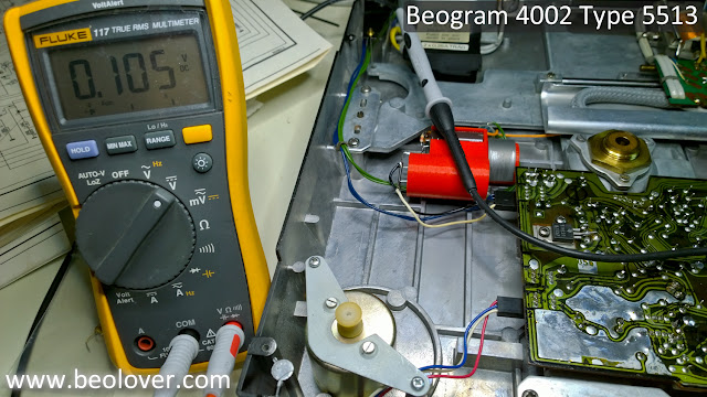
However, with this temporary replacement light source I am able to test out that the Beogram electrical updates are functioning as expected.
There were a number of tasks that had to be done when the tonearm carriage was removed so this was the first opportunity to test out those changes. This is always a good milestone in the restoration to reach. Tomorrow I should have the parts I need to finish the electrical adjustments. After that I can get on with the mechanical adjustments.


No comments:
Post a Comment
Comments and suggestions are welcome!