After a first evaluation outside (see my previous blog) it's time now to have a peek inside. The best way to open a Beomaster 6000 quad is to put the unit upside down. Flat on the main front panel. Be careful not to damage the key pannel and plexiglass front. Put something on your bench first to protect.
There are 7 screws to be removed from the wood plinth and the small nut that holds the big dial wheel. Once this is done, the plexiglass front will be loose and may fall out ! The key panel remains attached with a bunch of wires.
Now it's time to turn the unit back up and have a look inside.

Coupling capacitors, pre-amp and part of the output stage PCB
Motor control unit and tone amplifier. The panel is already upright in this picture. There are 2 screws (one left one right) that fix the control unit to the main chassis. They are not easy to spot. They are the only screws holding the complete motor control unit in place.
IF section
Decoder and relay trigger circuit
FM preset trimmers

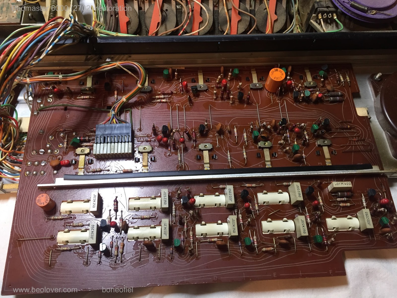
Electronic switch panel. The long metal bars (with the black insulation tape) hold the PCB to the main aluminium key panel. Remove the 2 small screws to free the PCB from the key panel.
Motor operation panel. (same as above)

Motor control unit. BE CAREFULL: the wires (in the red flexible "hoses") that are going to the magnetic clutches are very, very tiny wires and brake off easily (and hard to solder back). See also next picture.
Do you see what I see? Yes, the belts have been replaced with dial string cord ! And apparently this worked. But still, this is off course not "Beolove" and a new set of correct belts needs to be placed.
Looking further around and I spot some bad solderings on the indicator circuit PCB (the one with the stereo light, balance and FM signal strength meter). My guess is that the bulbs (wired) have been changed. The green and white/grey wires go to the FM illumination bulbs and often brake off if you try to swing open the FM dial board. I assume this is what happened, since the black screws holden the FM dial board are not the original ones. Some one opened it up and lost the screws. Happens a lot.....while it is so easy to keep a small box or bag to hold all the parts that you remove.
On to the dial cord. It's correctly placed on the (purple) wheel, the shaft and around the small wheels up to the FM main dial screen. But the dial is not moving....
And below you can see why. The dial cord is no longer attached to the dial band. The clip is broken. Again, someone did put some glue on it together with a piece of plastic in an attempt to keep the cord attached to the dial band. And it did not work !
When I removed the dial wheel, I also noticed that the pin in the shaft is not the original one. In fact, in most units that I've worked on this pin is broken completely or missing. But because the shaft is apparently very slightly tapered this does not pose a real problem. After tightening the nut on the shaft, the wheel stays firmly attached to the bearing house anyhow.
On to the 2 main switch panels (the motor control and the electronics switch). Not much to say, except dust, dust, dust... This is fairly common since the front panel "tongues" have small gaps where dust can easily penetrate. A vacuum cleaner comes in handy now....but be careful not to suck in small pieces that are not firmly fixed, like the white or red plastic covers on the glass bulbs. Happened to me before.... and searching in a vacuum cleaner dust bag is not a funny thing to do :-(


The key panel itself is an interesting design. In fact, this design construction in used in many other B&O units like the Beogram 4002 series or the Beocord 5000. Under the steel "tongues" are black plastic retainer blocks. They prevent the "tongues" to move upwards and at the same time interact with the (purple) plastic knobs (see pictures above) that again interact with the small electric switches on the board. These switches have a air gap of max 0,5mm when new. Over time, because of warping of the PCB's, metal fatigue of the switches, etc. the course of the tongues starts to change a lot. Also, in many cases the black retainers blocks just fall of. As a result you see the tongues bending upwards on the front key panel. Not a lovely view! Luckily, this is not the case here. In fact, the blocks have been re-enforced with extra glue!! This may pose another issue when I will have to remove them for further restoration of the key panel. But that is a worry for later.

The output PCB has the usual warping. This is very common and is often the reason for a short circuit with the chassis, causing the darlington output transistors to fry. After checking these transistors, the front right output stage was indeed fried ! Of all the Beomaster 6000 quad's that I have seen with bad output stages, 9 times of 10 it's the front right output. The only reason that I can think of is the fact that the components that drive the front right stage darlingtons are the closest to the chassis on a warped PCB. Thus the risk of short circuit is the highest in this area. I can't think of any other plausible explanation why the other channels usually don't fry.
To remove the motor unit I had to remove all the potentiometers. And to do this, the dial bands had to be removed as well. Care should be taken when removing these fragile bands and the pressure clips that hold them in place on the purple wheels. Beolover has 3D printed clips (in nice colours !) available if needed.
Now the complete motor unit can be removed
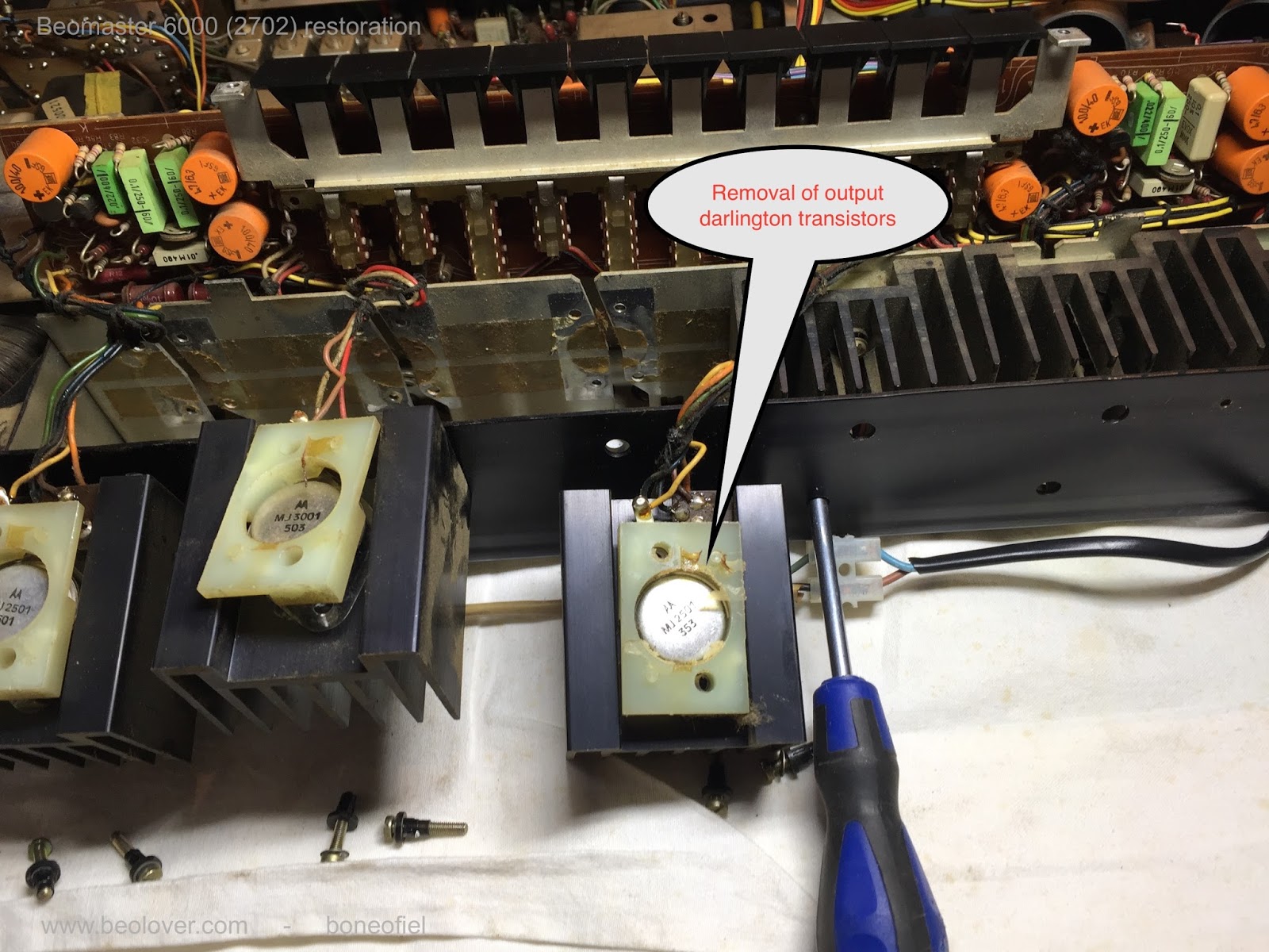
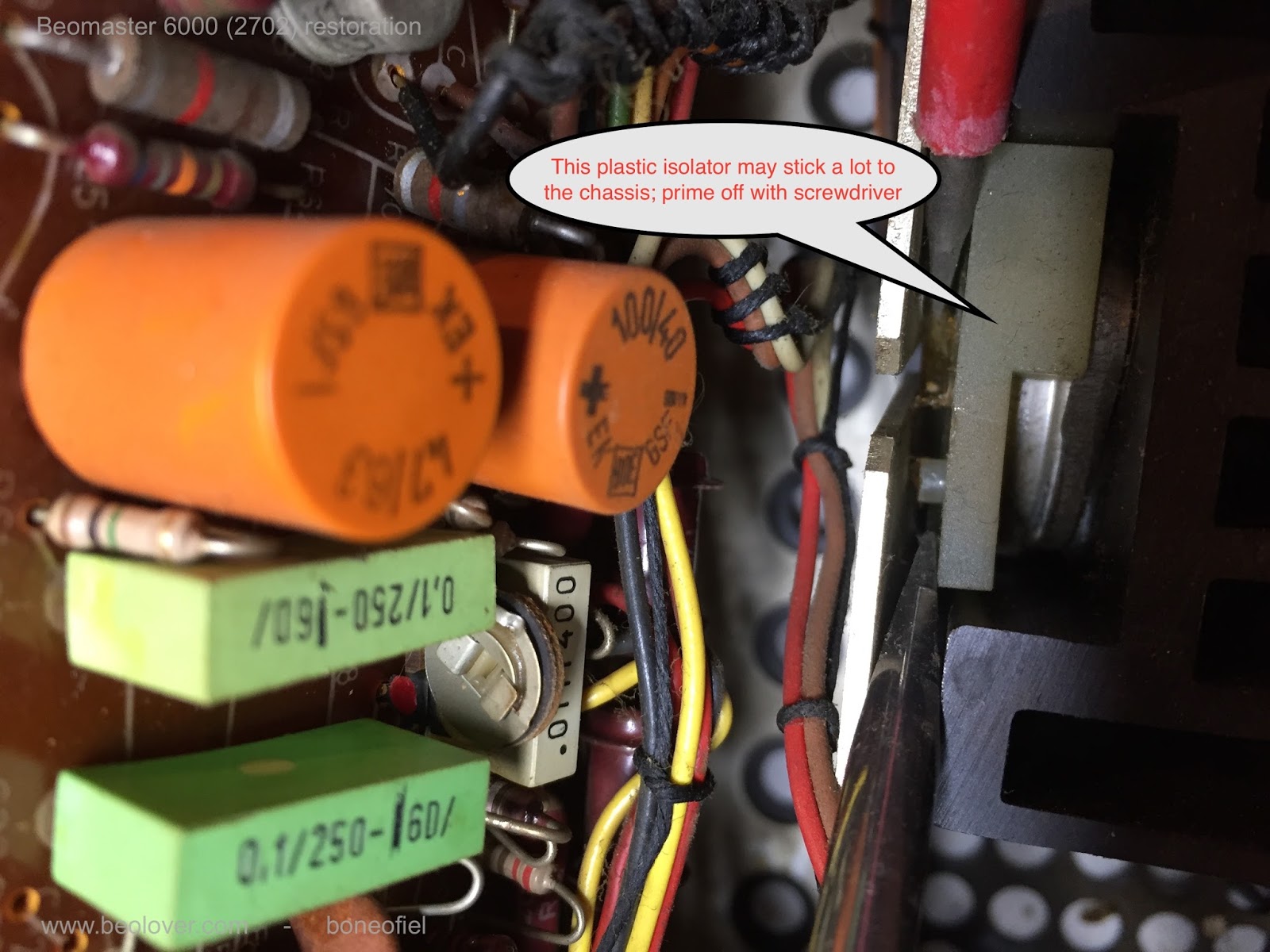
Time now to remove the 8 darlington output transistors. While it is not that difficult, one should know first how they are mounted on the chassis. The plastic isolators are lightly glued to the subchassis. You need to prime them of (e.g. with a screwdriver). This is the only way to get the transistor out with there cooling elements. While doing this, it is a good idea to lift the output PCB at the same time. This makes it easier to get the wires going the transistors out of the subframe.
The output PCB has a bank of black push buttons soldered on it. Each button has a tiny pressure clip to allow the push in/out movement. They brake very easily and are extremely difficult to repair or replace. Be careful !
Next is the ultrasonic receiver. First remove the 2 screws underneath the chassis and then it is easy to remove the PCB.
Same for the FM preset PCB. Remove the 2 screw in the chassis first.
To reach the power supply PCB, it is best to remove the main FM dial potentiometer and the relay first. By the way, not all Beomasters 6000 quad have this relay; so don't be surprised if yours does not have it. The same for the LED light on the front left (to indicate reception of ultrasonic signal), just above the ultrasonic micro receiver: some have it, some don't. This unit does not have it. In fact there are many other small differences made over the yeas. The problem is that only 1 version of the electric drawing exist to my knowledge. And only one type number designation: 2702. And that can be very confusing....Also serial numbers don't mean anything (at that time) serial numbers were given across the full production range so number 315674 could be a Beomaster and 315675 could be a Beovision or a pair of headphones.

Now you can remove the power supply PCB. Be careful, there are wires on all sides of this PCB: left, right, front and back…..I usually keep the indicator section PCB attached to the power supply board.
The decoder and relay trigger circuit PCB is removed next.
At this stage all the remaining PCB’s can be removed from the chassis together with there wiring. You need like 6 pair of hands to do this….Off course you need to loosen all the PCB’s from the chassis, as well as the subchassis with the speaker, input and antenna sockets first.
Later on, I will remove some more PCB's from the cable tree.
So, not much is left on the chassis now!!
Quick removal of the headphone sockets and the dial shaft.
To remove the metal frame that covers the transformer is a bit tricky. There are a few hidden screws. If you don’t know where to look, you may struggle a lot. The first 2 screws are close to the plastic housing that covers the main fuses. There is a copper foil glued to the frame. You need to peel of this foil partly to discover the screws.
Another screw is under the plastic cap that covers the on/off switch. Remove the cap first end then take out the on/off switch.
Now you can take of the metal frame that covers the transformer.
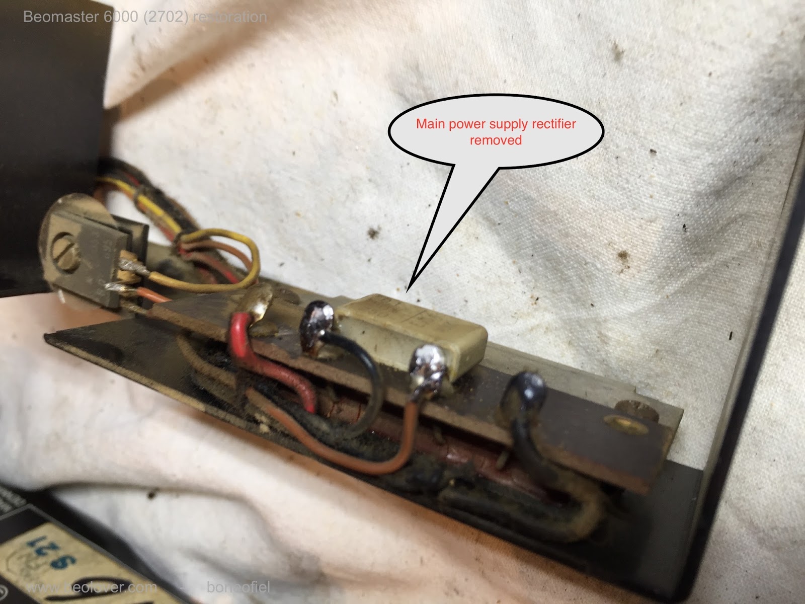
Before removing the transformer, take out the main rectifier and the cooling plate. There are 2 screws in the frame holding it together.
The transformer, together with the voltage selector can now be removed after unscrewing the big bolt underneath (put some WD40 first and let it soak for 5 min.) It is also possible to remove the clear metal subchassis in the main frame (4 small bolts holding it in place). Something I never noticed before.....
What is now left is a naked (dirty ) chassis!
and a lot of pieces..............
One thing I learned (again) is that when a seller tells you that the equipment he is selling is "in perfect working condition" and never been opened or repaired, be reluctant to believe him !! But this time it is not so bad, I've seen units in much, much worst condition.
Will I ever be able to put this all back together ??? Keep following my posts and you will find out.
Time for a pauze now.