In summer 2019 I
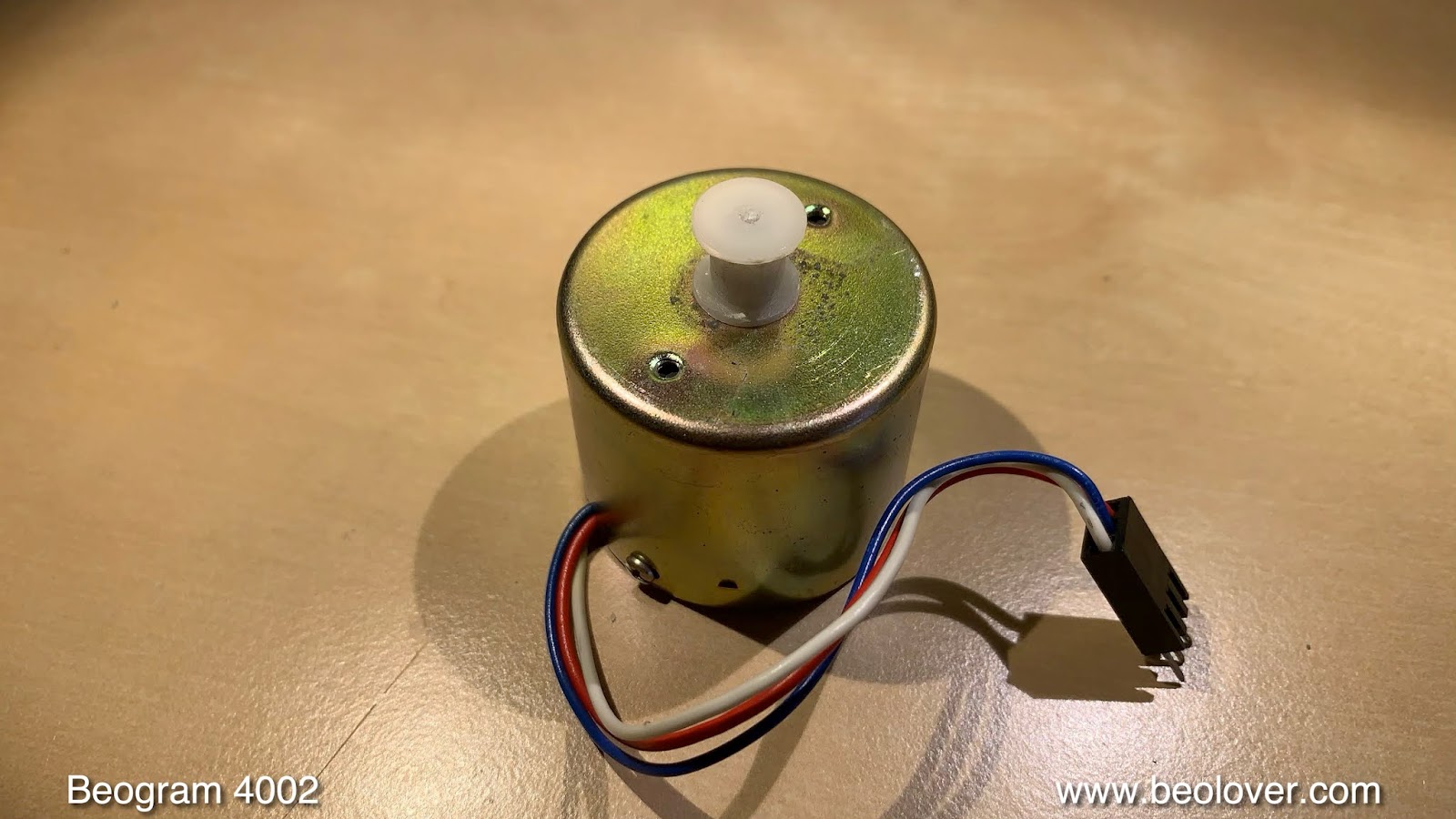
restored the DC platter motor of a Beogram 4002 located in Virginia. Recently, I received the entire unit for an overhaul. The restoration of the arm lowering mechanism had already been done, and I found it in good condition. So I focused one the remaining aspects of the restoration.
I began by restoring the main PCB. This shows it in its original condition:
I replaced all electrolytic capacitors and installed a new RPM relay as well as new 25 turn RPM trimmers:
My next focus was the record detection circuit. I now always replace TR4, the transistor that is responsible for amplifying the sensor signal, with a modern high-gain type (2N5089; Newark 33C8280) since in several recent restoration projects I found this transistor to be out of spec, usually with a too low gain. And this is dangerous for the needle, since the record detection circuit goes 'blind' if this transistor stops amplifying properly. This shows the original TR4, a BC183C:
I replaced it and also installed a 25 turn 5 MOhm trimmer as bias resistor. The circuit is pretty basic, and uses only one resistor between collector and base for biasing the base. When installing this trimmer, it is necessary to put it first on the solder side of the board that one can adjust it with a plugged in board:
The manual prescribes a collector voltage of 4V. After adjusting the voltage, I installed the trimmer next to the new transistor on the component side:
And that concluded the restoration of the main PCB:
The next step was to replace the main dual capacitance reservoir capacitor with two modern single capacitors held in place by a 3D printed fixture:
Then I took out the keypad to get to the output PCB:
Here I replaced the output relay and the capacitor that defines the time constant of the relay action. I also added a (red) switch that allows connecting system and signal grounds in case there are hum issues:
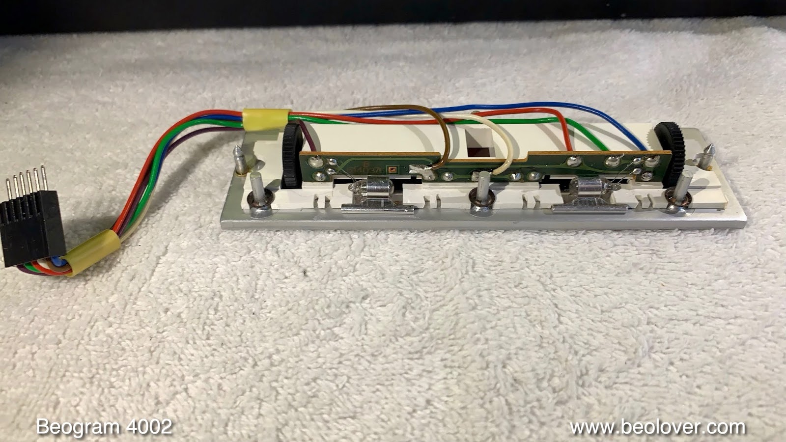
While the keypad was out, I also removed the RPM trimmer panel to replace the light bulbs with LED boards. this shows the panel with the original light bulbs installed:
and here with my plug-in ready LED boards
This shows the panel in action:
The LED boards are based on red-green LEDs that are tuned to give an incandescent glow. The red component ensures that the red indicators are properly illuminated. If one uses orange LEDs, the indicators appear grayish, since orange LEDs do not emit red photons.
My next focus was the replacement of the light bulb in the tracking sensor. The picture shows the original black bulb housing in place:
This shows my replacement part in comparison to the original assembly:
The LED is in the same place as the filament of the original light bulb. This shows the LED assembly installed during the calibration procedure of the tracking feedback:
The blue trimmer is very convenient for fine-tuning the tracking feedback by adjusting the light intensity of the LED.
This Beogram still had the original plastic pulley, that are prone to crack and fall off:
I replaced it with a precision turned aluminum pulley that was supplied by another B&O enthusiast from Vienna:
Looks awesome! If you wanted one for your Beogram, I'd be happy to get you in touch with the source. Just send me an email or use the contact form on the right.
Another often degraded plastic part in this Beogram 4002 vintage are the transport lock bushings. If they look 'orangish', chances are that they are crumbling. This Beogram was no different:
I removed all three:
And replaced them with SLS printed nylon bushings that come in two parts, one to be inserted from the bottom
And one from the top:
This shows the one on the left side installed:
And with the top retaining plate bolted back in:
After rebuilding the transport locks, I went after the last remaining incandescent bulbs of this Beogram, the one in the sensor arm:
I usually replace them with an LED circuit on a flex-PCB that folds into the small bulb compartment, and that draws a current similar to the original bulb. This current tells the circuit that indeed a light source is in operation. This shows the assembly installed:
The LED is a 'warm-white' LED that has a red emission component that preserves the natural look of the B&O logo at the end of the sensor arm:
Whenever replacing the light source in the sensor arm, it is advised to check the sensor signal at the collector of TR4:
The signal needs to go all the way down to 0V and have an amplitude larger than 5V. This sensor circuit fully matches these requirements, and therefore is good to go.
The remaining tasks were to replace the old corroded DIN5 plug
with a new all-metal gold plated type:
And to do the adjustments. The first step is usually to balance the sub-chassis, adjust the platter height and the arm distance. Then the arm adjustments need to be made.
Before calibrating the tracking weight I replaced the circlip that holds the counterweight adjustment screw in place with a M3 nut and a washer:
This allows locking the calibration in place after the tracking force is properly adjusted:
Another important adjustment is the arm lowering limit:
This is the last resort protection for the needle if the record detection circuit would ever fail and allow the arm to be lowered on a rotating empty platter. The limit needs to be adjusted that the needle misses the lower areas of the black platter ribs. These lower areas are strategically placed where the set-down points for 12", 10" and 7" records are.
Finally, I adjusted the RPM with the BeoloverRPM device:
And then it was time to take this restored Beogram for a first test spin. I selected a recently acquired vintage record by Ramsey Lewis, "Tequila Mockingbird", which he recorded in 1977 on Columbia Records (JC 35018). I love the inner sleeve where Mr. Lewis shows off his braces...ahh the 70s!!...;-):
It is rapidly becoming one of my favorite 'easy listening' records. Perfect for an afternoon while restoring a Beogram! Of course this record was ultrasonically cleaned with a
CleanerVinyl Pro Ultimate Kit on an Elmasonic P60H dual-frequency cleaner prior to listening. It now sounds pretty much like a newly pressed record. Beolovely!
I will now play this Beogram for a few more days and if nothing else comes up, it is time that it travels back to Virginia!