I recently received DC platter motor, main and output PCBs, and the Keypad of a Beogram 4004 from a customer in New Jersey for restoration:

Shipping went well, but please, do not put any tape on the keypad or any labeling!! These surfaces can be damaged when pulling off the tape. Luckily, in this case it went well, so no worries!
As usual, I worked first on the motor since the oil-infusion of the bearings can take up to 3 days. This shows the motor without its mounting plate:

I disassembled it to get the bearings out. The bearings are the two small donuts on the black pad upfront:

I submerged them in oil and pulled a vacuum. Immediately strong bubbling started:

The bubbling represents air drawn from the porous bearing material. Once the air is out, oil diffuses into the material. These bearings lubricate by slowly diffusing their oil content onto the shaft while the motor runs. At some point the oil is depleted, and that essentially limits the lifetime of the motor. Oil infusion under vacuum resets the clock! I wish old guys could do the same!...;-)
While the oil infusion was going on I worked on the remaining components. This shows the main PCB in original condition:

A detailed view of the RPM section, comprised of RPM relay and RPM trimmers:

I replaced all electrolytic capacitors, power transistors, RPM relay and trimmers and the sensor arm transistor:

Then I focused on the output board. In the 4004 it not only contains the output relay and delay circuit, but also the remote control interface for the Beomaster 2400, whose remote control is able to start and stop the 4004. This shows the board in original condition:

A detailed photo of the output circuit:

I replaced the electrolytic capacitors and the output relay:

This shows the output section magnified. I also installed a switch (red) that allows connecting signal and system grounds. This is helpful if there is a hum when connecting the Beogram to an amplifier:

Then I focused on the RPM panel above the keypad. This shows the panel extracted and flipped over:

Removal of the bulb covers reveals the incandescent bulbs that illuminate the trimmer scales:

In front of the bulbs the Beolover LED assemblies sit ready for installation. This shows the bulbs removed:

The LED assemblies solder directly to the bulb terminals:

This shows one of them magnified:

They do not obstruct the bulb covers, which can be re-installed after the switch:

Now it was time to install the components into one of my Beograms for testing. After bolting in the main PCB I replaced the two power transistors that are mounted on the solder side. Since their alignment is defined by the bolts that hold the PCB in place, it is best to replace them when the board is installed. This shows 1IC1 that controls the 21V rail:
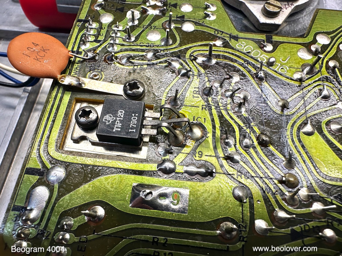
Ii usually is a TIP120 originally. I replace them with a stronger TIP102 hoping to increase longevity:

These modern TIP devices have a tendency to introduce high frequency oscillations superimposed to the 21V rail, and it is advised to add a 100nF capacitor (the yellowish component in the picture) at the emitter to quench this nuisance. I also replaced 1IC4 with a TIP107. The final step in the main PCB restoration was the adjustment of the bias of TR3, which amplifies the sensor signal. I usually replace the bias resistor with a trimmer. This allows compensating for the particular gain of the transistor. Once the bias is adjusted

to get 4V at the collector, the trimmer can be moved to the component side of the board.
Luckily, my customer sent the keypad along. After I removed the RPM panel, cracked panel holders were revealed. Both of them had the same stress fracture:


Luckily, there are faithful plexiglass reproductions available from the beoparts-shop in Denmark:

All that needs to be done before installation is to move the metal spring clips over from the original parts:

This shows the new holders installed:


Beolovely! Now it was time to extract the freshly infused bearings from the motor oil:

I re-assembled the platter motor and also installed it in my Beogram. Then it was time for RPM stability measurements with the BeoloverRPM device:

First I measured in the 'slow' mode of the BeoloverRPM, which yields an RPM measurement every 10 seconds. This is a great way to measure the long-term stability of the RPM. This is the curve I measured after 24 hrs:

Not the best result I ever saw. Such jagged curves are indicative of a top motor bearing that still needs to 'settle'. I am not entirely sure, but I think that the reason for such variations is a slight misalignment of the re-infused bearing relative to the original position. In my experience this will smoothen out after one or two hundred hours of play. Basically the shaft needs to polish the bearing anew in an orientation defined by the pull of the platter belt. At any rate, these current RPM variations that are pretty small, about 0.2%, which is less than what most people can discern.
There is an easy and quick way to a perfect RPM curve: Replace the original DC platter motor with the Beolover SyncDrive. The SyncDrive is based on a synchronous brushless motor, which completely bypasses the analog control system on the main PCB and instead uses a digital on board controller. The SyncDrive gives DC motor Beograms a wow and flutter performance equal to earlier AC platter motors with a long-term stability of later Beogram 8000/8002 models.
The next measurement used the 'fast' mode of the BeoloverRPM, where it logs an RPM value every time a platter rib passes under the sensor. In other words, every platter rotation yields 24 measurement points:

This is a graph that covers about 60 platter rotations (~2 minutes):

What we see is a repeating zig-zag pattern that is caused by minute variations of the rib spacing around the platter superimposed by a wavy waveform. It repeats exactly every platter rotation. This repeating pattern can be considered a measurement artifact that is not related to RPM changes. The longer wavelength wavy pattern however represents 'wow and flutter', i.e. RPM changes caused by the platter motor (and sometimes other factors). The main reason for this pattern is the feedback based RPM regulation of the DC platter motors. Basically, the control electronics continuously measures the RPM and when it is too low, the motor voltage is increased until the motor runs too fast, and then the system decreases the voltage. This usually causes sine wave shaped variations as seen here. All DC platter motors have this phenomenon. This is a common feature observed in all feedback based control mechanisms. The art of designing such control systems is to minimize these variations. But they cannot be fully eliminated.
At any rate this set of Beogram components is ready for duty again.
No comments:
Post a Comment
Comments and suggestions are welcome!