I recently received a Beogram 4002 (later Type 5501 with optical carriage position detection) for a technical restoration. It came without hood. This shows the Beogram after unpacking it:

Aside from a lot of 'goodies' that came tumbling out of the unit, I also could not help noticing that it had been packaged with the cartridge installed:

At least the little plexiglass protector had been stuck onto the MMC4000 cartridge, preventing damage. I secured the cartridge into a Belover MMC storage box:

Among the 'goodies' strewn around the enclosure I also found a small black box containing a MMC20CL cartridge!
This shows the unit with the tape removed and the platter added:

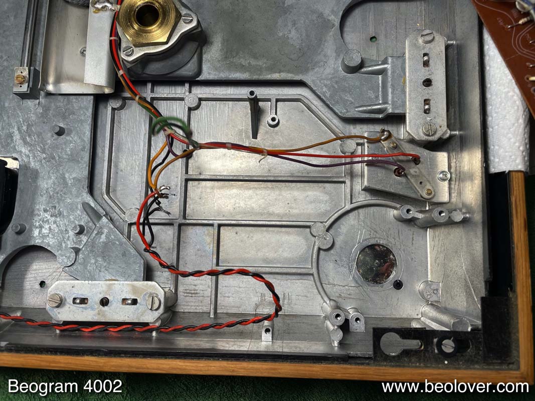
It is in pretty good condition overall! No major damages to aluminum surfaces, wood and keypad. Under the panels it looked original:

A great starting point for a restoration!
Throughout the enclosure I found the telltale debris indicating deteriorated transport lock bushings:
As usual for these Beogram Types, the plinth guidance washers also were degraded:

Also typical for these earlier 4002s is that the glue used for the keypad assembly gets brittle and the keypad components tend to come apart with little effort. In this case the pad itself had already mostly come off:

I also saw that the solenoid switch was missing its plastic tab (it should be on the pointing up corner that gets pressed down to switch it) that is needed to allow the solenoid lever to press down the switch arm:

Luckily, I found the missing plastic tab while working on the unit, so I was able to repair the switch (see below).
After this visual inspection I plugged the unit in and pressed START. The carriage started moving and the arm dropped at the LP setdown point. Also the AC motor showed signs of life. All good signs! I tried again but it returned home after moving for a few mm. I did it again, and again it did not go to the LP setdown point, but returned home instead. Strange. This indicated some issues with the control system. This would have to be followed up later when the electronics had received their standard restoration. I usually replace all the parts that are known to cause issues first before I start looking into 'unusual issues'.
I started the restoration process with the arm lowering system and the carriage mechanism. This shows the arm lowering mechanism as I found it:

I removed all the moving components and I also took the rods and the spindle out that enable the translation of the carriage:

Then I cleaned the parts thoroughly:

After putting everything back together, I started working on the main PCB. This shows it in its original condition:

I replaced all the electrolytic capacitors and the H-Bridge and AC motor driver related transistors since these tend to fail. I also replaced the transistor that amplifies the record sensor signal and put in a trimmer that allows adjusting its bias precisely. Also the RPM trimmers were replaced with modern 25-turn encapsulated units for precise and stable adjustment of the RPM. This shows the board after its restoration:

While the board was up, I also replaced the two power transistors of the push-pull stage of the AC motor. This shows the original TIP31 and TIP32 units bolted to the chassis for cooling:

I replaced them with modern power transistors:

Another trouble spot of these decks is the solenoid transistor, usually a TIP41A:
I already a had to replace a few of these in the past, so I added replacing them to my standard process. I replaced it with a new unit of higher voltage rating (TIP41C), which may be a good idea due to the fact that it drives an inductor:
Another failure point of the solenoid actuator circuit is the power resistor that limits the solenoid current after the solenoid has been activated. It sometimes goes open circuit preventing the solenoid from staying activated. This resistor is the somewhat strange looking white component in the picture:

The soldered wire on top is a primitive fuse that breaks the circuit in case the resistor gets too hot: The solder becomes liquid and the wires snap apart due to their tension from wrapping them around the resistor body.

I replaced it with a modern resistor with a higher power rating. I also replaced the capacitor on the board.
The final piece in the solenoid circuit restoration was repairing the solenoid switch, which connects the solenoid coil directly to ground as long as the solenoid is not fully actuated. This provides the large current needed in the solenoid to work against the springs in the arm lowering mechanism. Once the solenoid plunger is fully extended, it takes much less current to hold it down in that position. Therefore, the solenoid switch breaks the ground connection when pressed. This leaves the current only one path to ground, via the solenoid power resistor that I exchanged above. It is crucial that this switch works properly. If the ground connection is not broken when the solenoid is extended, a high current will flow through the coil even after the arm is down. After a few minutes this will heat the coil to a temperature which can damage the insulation of the windings and thereby short circuit the coil in parts. When that happens it needs to be replaced or re-wound. Not a promising path to go!
Luckily I found the missing switch tab in the enclosure. It was stuck under the output board. I extracted the switch PCB that I could extract the switch itself. It is better to glue the tab on when the switch is 'in hand', so it sits really flush on the metal part. This shows the extracted switch and the missing tab:

I epoxied it back on:

After letting the epoxy cure for 24hrs I re-installed the switch and then the board. This shows the switch with the solenoid at rest (I apologize for the fuzziness):

And with the solenoid actuated:

All good in the solenoid department!
Now it was time to focus on the output PCB that carries the output relay and the delay circuit for activating the relay (it prevents the touchdown noise from making it to the speakers when the arm lowers). This shows the board in its original condition:

I replaced the relay with a modern encapsulated unit. I also replaced the capacitor of the delay circuit and I installed a switch (red) that allows connecting system and signal grounds in case there is a hum-issue when connecting the Beogram to an amplifier:

The next step was to restore the AC-motor and main capacitor section. This shows the original setup:

I removed everything and cleaned out the compartment:
Then I took the motor apart for oil infusion of the bearings. This shows the extracted motor:

I drilled out the rivets and took it apart:

The beautiful simplicity of these synchronous motors continues to impress me. Just two coils and a rotor!
This shows the rotor with the components on the shaft shown in the order and orientation as they should be installed:

I submerged the enclosure parts in motor oil

And pulled a vacuum.
While the bearings were doing their infusion I focused on installing modern capacitors for replacing the old leaky units. This shows the Beolover capacitor assembly with the capacitors already prepared for connection to the wiring:

This shows everything back together. The motor was assembled after the bearings sat in the oil for about 2 days. The drilled out rivets were replaced with 3D printed brackets that now hold the bolts for adjusting the tilt of the motor:

After this it was time to replace the incandescent light bulbs with LEDs helping ensuring trouble-free operation in the years to come. This shows the original bulb housing of the tracking sensor:
I removed it. This shows the original bulb together with he replacement part:
I installed the LED assembly. The blue box is a trimmer for tuning the light intensity of the LED. This is helpful when adjusting the tracking feedback.
At this point I realized I had not yet lubricated the pivot point of the linkage that connects damper with tonearm. I removed the sensor arm

and took the linkage off (mind the small spring that is under the circlip if you do this at home - the spring likes to get lost quickly...;-).

Here you see the circlip reinstalled on top of the small spring after I cleaned and lubricated the shaft:

After this I replaced the light bulb in the sensor arm. This shows the original bulb in the small compartment at the end of the arm. Next to it you see the Beolover drop-in ready LED assembly together with its mounting support:

I removed the bulb and installed the LED assembly:

This shows it in action. The B&O logo is light up in its original color. This is enabled by using a special white LED with very warm color that has enough red component to act like an incandescent bulb:

The remaining bulbs to be replaced were in the RPM panel. This shows the RPM panel after taking the bulb covers off:

The brown spot on the left one (covering the 33 RPM backlight) is indicative of the heat load emitted by the bulbs. Since 33 RPM is mostly used the heat damage becomes apparent more easily on that cover. This emitted heat can cause sudden RPM changes due to thermal expansion of the RPM adjustment potentiometers located behind the small PCB that holds the bulbs. Replacement with cool running LEDs cures this issue. This shows the two small drop in ready Beolover LED assemblies:

They solder directly to the terminals where the bulbs are connected:

This shows the 33 RPM LED in action. The uneven backlighting is indicative of a wavy white background foil, another casualty of the high heat load emitted by the original bulb. Most AC motor 4002s have this issue if they were regularly used to play records:

This meant I had to take the panel apart to get to the white background foils. This shows the 33 RPM panel with the original foil. You can also see the LED board peeking out from behind:

I replaced both foils (for consistency) with white 3M electrical tape cut to shape (I just stick the original foils on the electrical tape and then cut around with scissors):

Now the background was homogeneous. Beolovely!:

Now I focused on the degraded transport lock bushings. This shows one of them after removing the top part of the lock:
I removed all the fragments from the orifices and then vacuumed all the small crumbles out of the enclosure. Then it was time to replace the bushings with 3D printed parts. Two of them combine to a full bushing. This is convenient, since one can simply stick one half into the orifice from the bottom, and add the other from the top:
This shows a pair installed:
and with the top plate put back into place:
Next were the plinth guidance washers. I usually replace them with these 3D printed nylon replacements. One is black, to be installed in the front center location, where it could otherwise be seen through the gap between aluminum plate and plinth were it white.

This shows one of the washers installed:

Now it was time to do the adjustments. As usual I started out with adjusting the floating chassis, platter and arms. After this process was completed it was time to adjust the tonearm lowering limit

and calibrate the tracking weight. For this I usually install a nut to secure the counterweight in place (originally there is only a flimsy circlip, which is not great if the calibration is supposed to survive shipping):

Then I calibrated the tracking weight scale to be precise around 1.2g, which is the tracking weight for most B&O cartridges:
Please, note that the scale on the tracking weight adjustment wheel should be taken with a grain of salt. It is always best to use a precision weight scale and adjust the weight with that and ignore the scale on the wheel.
On to the electrical adjustments and measurements. Here I adjust the bias of the sensor transistor TR9 that the collector is at 4V:

This shows the sensor signal at the TR9 collector with no record on the platter. A strong >6V pp amplitude is achieved, more than enough for disabling the arm lowering circuit in the absence of a record:

Each dip corresponds to a black rib moving through under the sensor.
A test with the platter on, unfortunately, demonstrated that the arm lowering mechanism however did not get disabled despite this strong signal. A bit of measuring and testing revealed that the transistor that relays the 'no record on platter' signal to the rest of the circuit, TR12, had an issue. I realized this since its Collector was always at ~8V. After replacing it with a new BC547B the circuit started working.
The next measurement was the motor voltage. This shows the signal for 45 RPM (57 Hz).

A nice sine wave as it should be!
I thought this restoration was nearing its end and that I would soon play a first record! So I replaced the original corroded DIN5

with a nice new all metal plug with gold plated contact pins:

After this I tried to play a record, but the deck showed a new strange behavior: After pressing START the carriage started moving, but none of the RPM backlights came on. The AC motor however was spinning at 33 RPM. When pressing either the 33 or 45 the respective backlight came on normally. This suggested that there was some major issue in the RPM circuitry. Since both backlights were affected, and they worked when pressing the keys, a consultation of the circuit diagram suggested that the two transistors that form a flip-flop to enable switching from 33 to 45 and back had lost the ground connection at their emitters.
This suspicion was confirmed after a close inspection of the PCB. I found a small crack around the mounting hole towards the fron of the Beogram:

This crack extended through two traces at about 11 and 5 o'clock. You can see it faintly on the above picture. This interrupted the continuity of the trace at 5 o'clock, but not (yet) on the one at 11. I scratched off some of the solder mask material aroudn the cracks and soldered small wire segments onto the trees across the cracks. This immediately fixed the issue and the deck launched normally again.

I stabilized the crack by epoxying a suitable plastic washer around the mounting hole. This should keep things together.
After this repair, I tried playing a record. This started out well, but after a few minutes the arm suddenly lifted off and the carriage returned home. I was able to reproduce this after a few attempts and it became clear that there was indeed an intermittent failure mechanism at work. It seemed the STOP function became randomly activated. Sometimes even before the arm reached the record. A look at the circuit diagram shows that STOP can be triggered either by the end switch or the STOP switch in the keypad, or by the "RUN-OFF-STOP" circuit that detects the run out groove of a record by 'measuring' the higher carriage velocity in this groove compared to normal play.
Since the switches seemed to work properly, I looked in more detail into this circuit. I measured the voltage at C33, the capacitor that sums up the current pulses that come through the Greinacher circuit from the collector of the optical position sensor transistor TR23. Everytime a black bar passes through the sensor a current pulse is transmitted onto C33, which causes its voltage to increase. This is compensated by a discharge mechanism via R84 and R85. If the pulses come quickly enough, the voltage gets high enough to turn on TR22 and STOP is triggered via the base of TR19. This is normally only possible if the dense line pattern on the 'plexiglass ruler' of the position sensor system is quickly pushed through the sensor as the arm drags the carriage through the end groove.
I hooked up the oscilloscope to C33 and had a look at its voltage. After a few trials I was able to reproduce the phenomenon again, and C33 showed this voltage behavior, while the STOP function was triggered:

Clearly the capacitor was charging, and there were at least two pulses that added up to the large signal exceeding 3V. Usually if the voltage goes higher than ~2.7V the STOP function is triggered. During normal run off it takes 2-3 bars to pass through the sensor that the voltage adds up enough to trigger the function.
Anyway, here the pulses had to come from elsewhere, since the ruler was clear as it passed thorugh the sensor, while the above happened. So I put my money on an intermittent connection between the sensor and C33. Luckily, I started from the C33 side, and while I moved the measurement lead from one solder point to the next (in order to watch the oscilloscope, while the deck was running and then STOPping), I got already lucky at the C34 solder point on its TR23 pointing side! After I soldered the lead to it, the phenomenon was cured! This meant this solder point was intermittent, and soldering the lead to it re-flowed the spot and thereby fixed it.
Now the deck finally fired on all cylinders!
So it was time to characterize the RPM stability of the AC motor. I did not have access to my normal BeoloverRPM device since I did this restoration while vacationing in Germany, and so I used an experimental design I am currently working on, which has a platter speed detector integrated to measure the usual RPM stability curve

This is the curve I got:

An excellent result, which was pretty much expected since this is an AC-motor Beogram!
The final issue that needed to be fixed was the falling apart keypad. I encouraged the aged contact cement to give up completely, and I separated all the components of the pad:

Then I glued the components back together with modern contact cement. First I put the plastic stops of the front five buttons back on:

Then I added the back plexiglass plate, and after glueing the keypad in with the five already installed stops, I added the remaining two on the backsides of the 33 and 45 RPM buttons:

This put the keypad assembly back into business:

And finally it was time to give this beautiful deck a first play. I selected a lovely Blue Note release by Art Blakey and the Jazz Messengers that my father has in his collection: "meet you at the jazz corner of the world (Volume 2)" (Blue Note 84055; it seems it is a 1975 reissue, judging from the label style on the vinyl)

Beolovely! I will now play this deck for a bit longer, and if nothing further comes up it is time to send it back to its owner!
No comments:
Post a Comment
Comments and suggestions are welcome!