My break from the workbench is over. Time to resume and wrap up this Beomaster 2400 restoration.
I left off with the discovery that the right channel output amplifier was distorting.
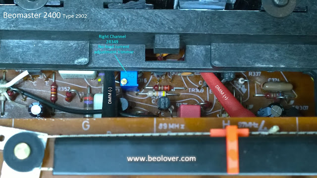
In resuming work on this Beomaster I removed and tested all of the right channel output amplifier transistors out of circuit. It wasn't any surprise that they all tested good since the right channel was working at low power levels. That being the case I decided to replace all of those transistors in the right channel along with the two emitter resistors. I also wasn't happy with the single-turn trimmer resistors I had installed for the no-load current adjustment. The single-turn resistors are fine but I prefer a multi-turn resistor for that particular adjustment. It is easier for me to dial in the correct value and feels more precise.
Here are pictures of the transistors that were replaced and the new trimmers.
The new multi-turn trimmers made re-adjusting the no-load current adjustment a breeze.
Now it was time for checking the left and right output amplifier channels THD again.
This type of measurement poses a problem regarding my stating that the THD for this amplifier is exactly per the service manual published technical data.
For one thing, the published audio specs stated by various manufacturers are a little vague. They often quote DIN specs that they followed but details of those specifications are difficult to find. Even then, the measurement equipment is different now.
My methodology is to use the manufacturer specs as a guide but measure all of my amplifiers using my own same test setup and same measurement devices. That gives me a set of data I know the source of and can use for comparison.
I have shown this before but here is my test setup.
I use a fixed, dummy speaker load of 8.08Ω on each channel. The 0.08Ω part of the load is a series sense resistor that I can connect my audio analyzer probes to for making power signal measurements with. The audio analyzers have limits on the AC voltage they can handle. While my QuantAsylum QA401 analyzer does have built in attenuators I still need to be careful.
The test connections go to my signal generator, QA401 analyzer, multimeters, oscilloscope, dummy load restistors and the amplifier under test (BM2400 in this case).
I use the multimeters to verify the AC signal the amplifier is outputting to the load resistors.
The Beomaster 2400 doesn't have a volume control that you can tell the precise volume level you are on. It does have three preset volume levels you can select from on start up though so I usually use those. Then I use the amplitude adjustment of the test signal generator and check the amplifier output with the multimeter to dial in a precise measurment output. The oscilloscope also aids in monitoring the actual input signal and amplifier output signal.
The QA401 audio analyzer measures the THD.
Here is a quick look at the Beomaster 2400 service manual technical data.
I am only interested in the rated power output and the distortion data.
Bang & Olufsen states here that they used DIN 45 500 for their measurement specification. I don't have those specs and I'm not sure they would really help me with the test equipment I have on hand.
So I will use the technical data that says this amplifier should be able to output 20W into 8Ω speaker loads. It should do that at a THD value close to what the THD is at lower output power. My dummy loads are fixed resistor loads and that is fine as I use those on all of my tests. Plus I am collecting my own measurement data for apple to apple comparisons.
The service manual stated harmonic distortion spec of 1000Hz, 50mW : <0.07% seems kind of odd.
I am reading that to mean a 1000Hz test sine wave input and the Beomaster output set to only 50mW across an 8Ω load. That is only about 0.6Vrms.
I decided to go ahead and make that measurement anyway but I still will do my own THD measurement at the full 20W output.
Here is the 50mW THD measurement for the left and right channels of the Beomaster 2400.
Both channels are in the 0.035% range which is well below 0.07%.
So if that is what the published spec meant then great.
For my own full power test at 20W of amplifier output across the 8Ω loads I get this -
This is what I wanted to see. The left and right channels are both performing close to each other and at a respectable THD of around 0.04% (at full rated power).
The Beomaster 2400 heatsinks do really warm up at this output level and normal listening level for the amplifier is probably down around 1W to 5W.
One last note about just doing the THD measurements here. Most of the time restorers rely on listening to known, good music sources through known good speakers to check the result of an audio restoration. That is fine and an important test to pass. I just feel more comfortable in having a repeatable instrument measurement test as a means to check that there isn't something hidden going on and that both channels measure close to what my other restorations have been. It paid off in this case because this Beomaster sounded fine in my initial listening tests after the recap but the higher power testing revealed a problem.
This amplifier is ready to move on to the final functional tests.
Those are where I will connect up a Beogram and Beocord then play the Beomaster 2400 for several days continuously (most of the time using FM as the source).


