The Beomaster 4000 that I recently outfitted with a toroid transformer came with another Beolove challenge piggybacked into the box: A broken Beolink 5000 remote control, which had a detached LCD screen. Unfortunately this Beolink 5000 was beyond repair since the LCD screen had mechanical damage at the contacts end, probably due to a fall of the display on a hard floor or similar.
We decided to not give up but rather try to procure a potentially fixable unit from ebay. Luckily, a few weeks ago a 'lot' of three Beolinks became available with the promise that one of them was actually still in fully working condition. My customer won the auction and had the units shipped directly to my bench. Unfortunately, it turned out that the LCD screen of the working unit also was already loose,
but it had not detached yet from its ribbon cable. Luckily, the seller had the presence to tightly wrap this unit so the screen stayed where it was during shipping and it did come alive when I put batteries into the unit:
I decided to develop a fix for glueing the display back into the remote body without breaking the very flimsy plastic foil ribbon connector that connects the LCD display to the circuit board. In fact this particular design feature seems to do in 99% of the Beolinks since it simply rips off when the screen detaches and falls out due to ageing glue. The glue seems to be the same foamy stuff they used for attaching the aluminum cover to the Beogram 8000/8002 turntables, i.e. it is no surprise that the LCD screens also pop out at this point in time.
Anyway, the task was to not kill the ribbon connector, while handling everything and cleaning the old glue out etc...It was beneficial that I had the two other units with completely detached screens to practice on. I used them to develop a 'tool set' that would allow me to do the repair with minimal mechanical stress on the ribbon connector.
Here we go:
I opened the unit up:
Then I carefully pressed the LCD screen out of its frame and moved the PCB and screen a bit to the left to release the board from its tabs on the right. Once the two parts were liberated I supported them with a custom designed 'brace' that would stabilize them in their relative alignment:
I applied the matching top part:
And flipped the entire 'assembly' over to the right:
Now I removed the board-to-board ribbon cable from the display control board:
The two tabs left and right of the ribbon can be pulled out and then the cable comes out:
This liberated the display part allowing me to go to work on removing the glue from the display frame:
The next step was to remove the glue from the LCD. The orange part of the brace now served as support during this procedure. I had designed a screw hole into left side of the orange part that allowed me to bolt down the circuit board to make sure there was no movement between LCD and PCB to protect the ribbon:
After cleaning off the glue it was time to install some industrial strength double sided tape in the frame. I had developed two more 3D printed parts that would allow me to apply the tape and then cut it to size with precision to not impair the translucency of the screen:
and with tape applied:
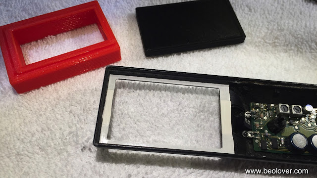
Then I cut the 'window' out of the tape layers using a razor blade and a matching 3D printed part that fit exactly into the display bay from the top:
This was the end result:
after removing the tape backing
Then I reconnected the display board and flipped it over with the braces in place:
After carefully pulling out the red brace part, I pressed the display into its bay, making sure that it was aligned properly:
And then came the moment of truth! Did the ribbon cable survive this stressful operation? After putting the keypad back on and inserting the three batteries it turned out that the operation was successful. The unit came alive again!
The next step is to figure out how to repair completely detached screens...another day, more Beolove!


This was a really helpful blog post about replacing the LCD screen on a Blink 5000 remote. Your detailed step by step guide of opening up the unit, moving parts around and reattaching the screen was really easy to follow, and the up close pictures of each step were incredibly useful. Thank you for posting!
ReplyDeleteRaymond @ CKS Global Solutions LTD
Your DIY repair tips come in so handy. I don’t have to go to the stores or contact their manufacturers as often. Your latest blog about gluing a damaged LCD screen down was especially interesting as it’s so amazing just how little it takes to repair a piece of technology.
ReplyDelete