Featured Post

Beolover SyncDrive: DC Platter Motor Replacement for Beogram 4002 and 4004 (Type 551x and 552x)

Late Beogram 4002 and the 4004 (Types 551x and 552x), which have DC platter motors instead of the earlier synchronous AC motors usually suff...

Showing posts with label sn3159045. Show all posts

Friday, December 3, 2021

Beomaster 5000 Type 2323: [UPDATED] Solving a troublesome mechanical door latch problem

 I have seen owners of Beomaster 5000 receivers complain on various forums about problems with the control panel door. The door either won't respond to the "Open" button command, is slow to open or won't close properly.

This Beomaster 5000 receiver had all of those symptoms. Pressing the "Open" section of the front press-bar would often do nothing. No click from the internal door latch solenoid could be heard.  Sometimes it would seem to magically engage the solenoid but then the door would either not open or just slightly open.
Then, finally, closing the control panel door would often result in the door not latching closed.

If the door never operated the solenoid I would suspect the electronics as there is a ribbon cable from the main electronics of the Beomaster 5000 to the control panel door. Sometimes that ribbon cable fails over time and has to be replaced.

In this case the ribbon cable is still functioning and the problem was a mechanical issue.

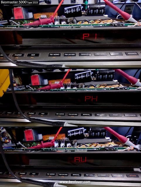
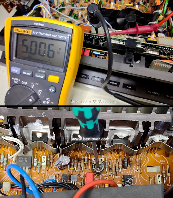
Here is a picture of the Beomaster 5000 turned on with the control panel door closed.


Pressing the open part of the control panel bar (shown highlighted in the photo) would bring disappointment (and frustration) in the door not opening.

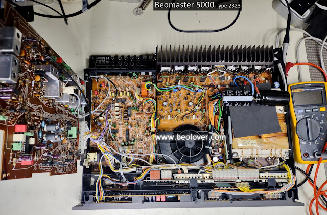
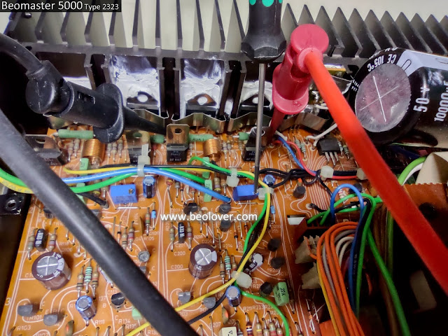
With the Beomaster top cover removed I could observe some of the activity that goes on when the door is being operated.

This photo shows some of the key components and how far the door would try to open during the times that the "Open" button got the control solenoid to engage.  It didn't have enough force to open fully.


I checked several things first.

The control panel door damping mechanism controls the opening of the door so that it slowly and gently opens up.  I checked that the damping mechanism wasn't hanging up and was correctly configured.

In this case it was good.

The photo below shows the door open actuator that the door bar presses against to release the door.
That actuator is spring activated and simply presses a rod that moves the metal door inward.
When the press bar is released the spring returns the bar to its normal position.
Pushing on the press bar also moves a plastic actuator to press against a flat, metal contact located on the keypad circuit board (PCB 5).
That is the actual, electrical button component that operates the door latch solenoid.

This photo shows what a disassembled Beomaster 5000 control panel door looks like from behind the "Open" press bar.


I noticed that when I applied pressure to the back of the control panel door (the black plastic frame) as I pressed the "Open" section of the press bar that the solenoid would always engage.

So electrically it appeared that everything was good.

Another issue with the door opening is that the door would not fully open up when it was unlatched.
Once the door is unlatched there is a center spring in the center of the door hinge rod that presses against the cabinet base and causes the door to flip open.

Here is what that spring looks like.


The spring is intact and it is pressing against the metal part of the cabinet base so that is not the source of the door not fully opening.

Checking the attachment points of the panel door hinge rod along the bottom of the door I discovered that there are two key mounting/pivot points.  It also looked like those two pivot points were sticking.

I worked in some dry lubricant and the door panel became much easier to rotate open.
Now an unlatched door rotated completely open.


That left the "Open" function intermittent operation and the problem with latching the door closed.

It turns out that those were related.

Here is a look at how the Beogram 5000 control panel door latch/unlatch mechanism works.
This is a photo of a disassembled Beogram 5000 front panel.  It shows the solenoid and the lever that latches and unlatches the control panel door.


Here is a closer look at the solenoid that operates the unlatching.


Looking at the catch for the door here are photos from the top looking down at the door latched and unlatched.


When observing these mechanics operating during latching and unlatching I initially thought there were two problems.

One of course was the unlatch solenoid operation being intermittent.
The second was the plastic door catch would often not move well enough to latch and to unlatch the door.

After many iterations of operating the door I found that if I helped the door panel "Open" actuator by holding the back of the panel firm, the solenoid would engage and unlatch every time.  It wasn't intermittent under that condition.

The door catch would also sufficiently move to unlatch and let the door open.
Surprising the latching function also improved.

Re-examining the "Open" push bar operation and comparing this Beomaster 5000 with the photo of a disassembled Beomaster 5000 control panel I realized this Beomaster panel has a missing plastic tab.

Here again is the photo of a disassembled control panel.


Here is a photo of the Beomaster 5000 door with the intermittent operation problem.
Notice the missing tab.


That explains why the door works when I manually hold the black plastic frame in place when pressing the "Open" press bar.  When the missing tab or my finger is not keeping the plastic frame secure it will move with the press bar and fail to engage the open door button contact.

The next problem was how to fix the faulty door mechanics.

After some more testing iterations I decided that I would try supporting the control panel door compartment behind the left side of the panel, where the "Open" actuator is, with a cut-to-fit rubber block.  I considered just gluing the keypad circuit board (PCB 5) where the missing tab is but rejected that idea because I wanted to keep PCB 5 where it can be easily removed if future repairs are ever necessary.

There is plenty of room behind the panel door for a rubber block and it would be like my finger in supporting the back of the panel.
Here is the rubber block glued in place.


The result is a success. 

So far the door opening mechanism works 100% of the attempts.
The door latch operation also works properly now.

I believe that too much flex developed on the left side of the control panel door, press bar over time.
That caused the mechanical operation to become unreliable.
The rubber block is providing needed support when the press bar is engaged so the latch/unlatch lever can fully travel and complete its task.

Here are a couple of photos of the working control panel door.


A few important things to note after wrapping up this issue...
  1. A completely non-functioning door unlatching problem (solenoid not working) could be an electronic problem involving the ribbon cable.
  2. When working on the door latch/unlatch mechanics, avoid the temptation to try and solve the problem with oil or other lubrication. The solenoid and its lever assembly work better dry.
  3. There could be a need to lubricate the mounting/pivot points of the long, door hinge rod. In that case use a dry lubricant like Tri-Flow Dry Lube.
Now back to my listening tests.


Thursday, December 2, 2021

Beomaster 5000 Type 2323: Final adjustments and testing

The Beomaster 5000 (Type 2323) service manual has some adjustment procedures to calibrate the volume level for the left and right channel stereo outputs and for the bass and treble levels.

Unlike older style amplifiers the Beomaster 5000 has pushbutton up and down buttons for volume, bass and treble.

The calibration of those volume controls uses a 175mVrms sine wave test signal input to the Beomaster 5000 Tape 1 source. 

For Left and Right channel volume calibration the test signal uses a frequency of 1000 Hz.
For the Bass level calibration the test signal uses a frequency of 40 Hz and for the Treble level calibration a frequency of 12,500 Hz is used.

The adjustments are made on the PCB 3 : Preamplifier board.

There are trimmer resistors for the Left and Right volume levels and for the Bass and Treble levels.

The execution of the calibration procedure is to set the Beomaster 5000 tone control setting to Neutral (no tone controls).  The volume level for the Beomaster is set to its maximum level (6.0) and the input source selection is set to Tape 1.  The test points (TP100 and TP200) should measure 4.2 Vrms when the levels are adjusted properly.

Here is the test setup...


The volume level adjustments and measurements are made using TP200 (Left Channel) and TP100 (Right Channel).

Here is the measurement using the 175mVrms, 1KHz sine wave test input on Tape 1 and measured at TP200.  The desired output is 4.2 Vrms.


I made the same adjustment and measurement on TP100 for the Right channel.

For the Bass level adjustment the Tape 1 input test signal is set to 40 Hz (and 175 mVrms).
The output is measured at TP200 only for this adjustment.  Again, the target output is 4.2 Vrms.


The Treble calibration is similar to the Bass adjustment except the Tape 1 test signal is changed to a frequency of 12,500 Hz.


That wraps up all of the adjustments I am going to do on this Beomaster 5000 receiver.

The next tests were to use my QuantAsylum QA401 Audio Analyzer to do a quick check of the amplifier audio outputs for the left and right channels.

As I normally do I run a test for Total Harmonic Distortion (THD) using a sine wave test input of 1KHz and the output amplifier at its rated output across a dummy speaker load of 8 ohms.

The input source I selected for this test is the Beomaster 5000 AUX input and I decided to use an input amplitude of 0.316 Vrms (-10dBV on the audio analyzer).
I want to check the THD for the left and right channels with the output amplifier running at 55 Watts.

Note: Because of the way the volume level steps in the Beomaster 5000 I had to adjust my input voltage up a bit to 0.332 Vrms (-9.5dBV on the audio analyzer) in order to hit my target output of 55 Watts.

Another audio analyzer test I will run is a frequency response test, also at the rated 55 Watts.

The Beomaster 5000 measured great on both tests.
The THD levels were well below the value stated in the service manual of <0.09%.
The Frequency Response was nice and flat from 20 Hz to 20,000 Hz not varying by more than ±1.5 dB.


The actual music sound from the Beomaster 5000 is the important thing of course.  It is also the fun part of an audio component restoration.

I have now listened to this amplifier for over forty eight hours and it plays beautifully again.

I still have to finish exercising all of the input source options before I am ready to send this unit back home.


Thursday, November 25, 2021

Beomaster 5000 Type 2323: Reassembly and initially power on test

The Beomaster reassembly went smoothly.  You do have to remember to reassemble things in the reverse order they were removed as the order is important.

Once the components were all put back in place it was time to try the always fun initial power on test.


On this initial test my plan is to verify some key voltages like the +5 VDC to the Microcomputer PCB and the ±40 VDC rail voltages for the output amplifiers.  I also will adjust the idle current trimmers for the output amplifiers per the service manual.

With the Beomaster 5000 plugged in I turned it on by selecting a few of the source selections.


That is always a good sight to see.

Obviously the Microcomputer is working but I still measured and adjusted the +5V power supply for it per the service manual.


Next I adjusted the output amplifier idle current to 11mV across each channel's emitter resistors per the service manual.


The multi-turn trimmers make those adjustments very easy.

The final test on this initial power up was to check the 40V rail voltages on the output amplifiers.


The initial power on checks all look good.

I can move on to the next round of testing which will include playing some actual music content through the Beomaster and driving some speakers.  I will also hook the Beomaster up to some test equipment and check what the audio signals are looking like on the analyzer.

Saturday, November 20, 2021

Beomaster 5000 Type 2323: Capacitors, relays and no-load current trimmers replacement

The restoration of the Beomaster 5000 (Type 2323) requires replacing quite a lot of parts. 
It is nice that Bang & Olufsen engineered this receiver so it is easy to get to the boards but there are a lot of electrolytic capacitors that have to be replaced. 
The circuit boards on these receivers also have very delicate traces. It is difficult to desolder many of the capacitors without incurring some lifted solder pads.  In those cases I beef up the connections between the parts with some added jumper wires.

Here are the before and after photos of the circuit board restoration on this Beomaster 5000 unit.

PCB 1 : AM/FM board

Before


After 


PCB 2 : Output Amplifier and Power Supply board

Before


After 
Along with the capacitors I replaced the left and right channel no-load current adjustment trimmers.
I also replaced the power relay.


PCB 3 : Preamplifier board

Before


After
This board had quite a few non-polar type electrolytic capacitors.
The preamplifier board also had a relay (for muting the speakers) that I replaced.


PCB 4 : Microcomputer board

This board had several axial type capacitors and it had a 3V Lithium battery that I replaced.


PCB 6 : Cooling fan regulation board

Before


After


PCB 9 : Remote control board

Before


After


Now that the old parts that needed replacing are all replaced with new parts I can begin re-installing the circuit boards and prepare the Beomaster 5000 for some bench testing.

Sunday, November 7, 2021

Beomaster 5000 Type 2323: Assessing a new Beomaster restoration

After what seemed like a long period of Beogram restorations I have retooled my workbench to do some Beomaster restoration projects. I have some Beomaster 4400 receivers to tackle but before that I decided to restore a nice Beomaster 5000 Type 2323 for an original Beosystem 5000 system owner who previously sent me a CD50 to work on.

This Beomaster 5000 receiver is in nice shape but stopped working this year.  It is actually quite impressive that it was still functioning up to this decade considering the Beomaster was produced thirty-five years ago.


I love the way Bang & Olufsen designed these series of cabinets.  Simply moving two screws upward at the back of the cabinet releases the catches that secure the cover.  When the screws are fastened in the up position the cover can slide off.


Here it is with the cover removed.


There is a little bit of dust but the Beomaster inside is surprisingly clean after thirty-five years.
You can tell it was always in a good environment for electronic equipment.

Flipping the unit over I removed the bottom panel.


Now a flip back to the top side where the components can be removed for examination and restoration.

Another nice feature of this receiver cabinet is how modular it is and how easy it is to get to components.  The top PCB (PCB 1 - AM/FM board) unbolts and flips up to a service position and reveals the preamplifier board (PCB 3) underneath.


At the very front of the Beomaster 5000, behind the display panel, are boards 7 (Display-right), 8 (Display-left) and 9 (Remote control).


With the front panel pulled out of the way the Microcomputer board (PCB 5) can be accessed and removed.  It is held in place by two plastic holder pieces that pull out from the top.


After the plastic board holders are removed the PCB 4 connectors can be disconnected and the Microcomputer board removed.


There are four electrolytic capacitors and a 3 volt lithium battery that will be replaced on this board.

The next component assembly to remove is the fan assembly.  Yes, with the compact size of the cabinet and the fact that the Beosystem 5000 components are expected to be stacked on top of each other, B&O installed a temperature sensor and a cooling fan.


The next assembly to remove is the plastic housing for cooling air to flow to the output amplifier board.


That assembly can be a little tricky to get opened up as the two large power supply filter capacitors have to be rotated to uncoil the three wires they are connected to.  When the wires are uncoiled there is enough room to move the plastic housing out of the way (and to remove the two filter capacitors for replacement).

All of the boards that have electrolytic capacitors I will remove are accessible now.

The Preamplifier board is easy to get to.


So is the power supply/output amplifier board.


You can see in the photo that the large relay on the power supply board looks a little charred inside.
That is typical on these amplifiers. After years of arcing during power switching of the Beomaster the relay contacts get pretty charred. I will replace this relay with a brand new one.  There is a matching speaker muting relay on the Preamplifier board that I will replace as well.

Here is the power supply/output amplifer board removed and ready to be worked on.


Now I have to make sure I have all the necessary replacement parts (there are about 71 capacitors to replace)...then I can start on the restoration tasks.