The Beomaster reassembly went smoothly. You do have to remember to reassemble things in the reverse order they were removed as the order is important.
Once the components were all put back in place it was time to try the always fun initial power on test.
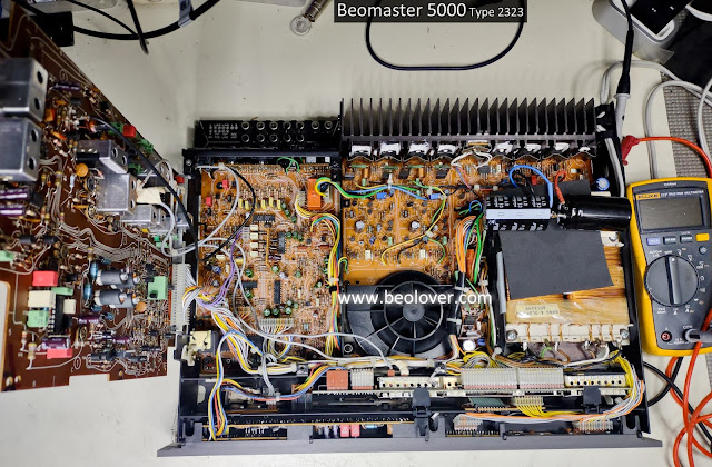
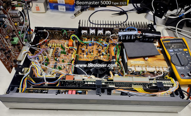
On this initial test my plan is to verify some key voltages like the +5 VDC to the Microcomputer PCB and the ±40 VDC rail voltages for the output amplifiers. I also will adjust the idle current trimmers for the output amplifiers per the service manual.
With the Beomaster 5000 plugged in I turned it on by selecting a few of the source selections.
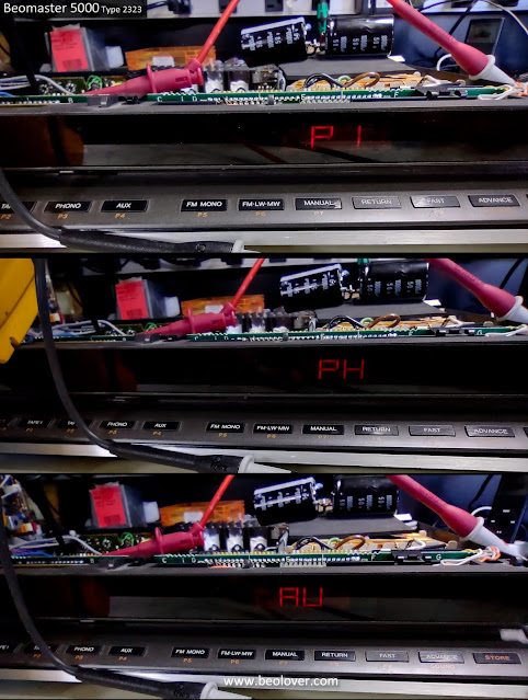
That is always a good sight to see.
Obviously the Microcomputer is working but I still measured and adjusted the +5V power supply for it per the service manual.
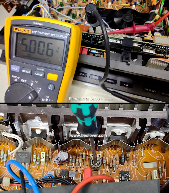
Next I adjusted the output amplifier idle current to 11mV across each channel's emitter resistors per the service manual.
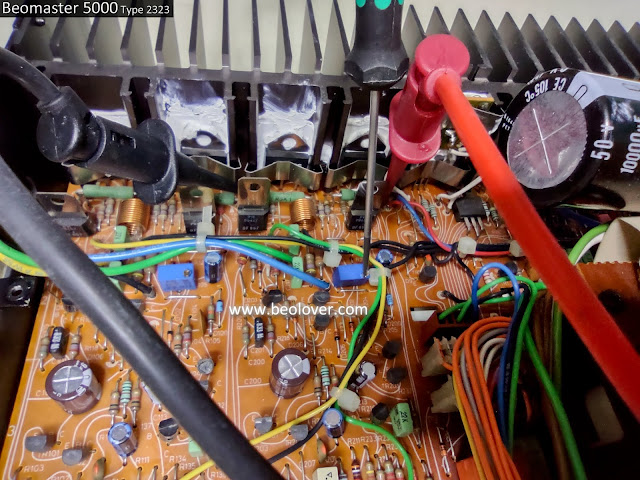
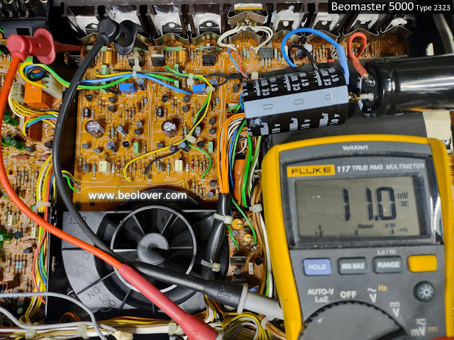
The multi-turn trimmers make those adjustments very easy.
The final test on this initial power up was to check the 40V rail voltages on the output amplifiers.
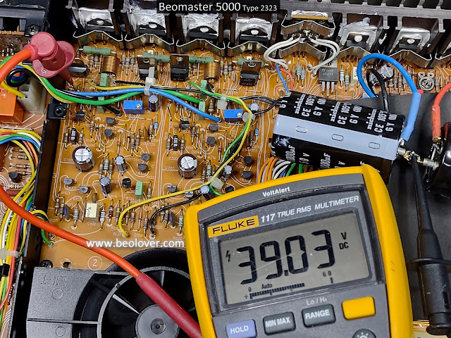
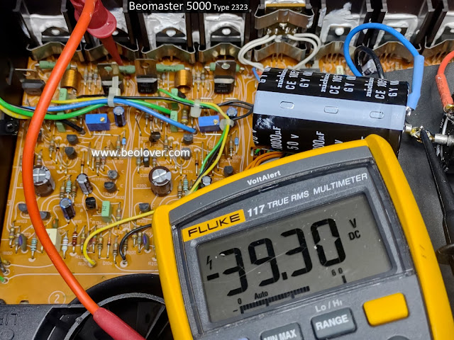
The initial power on checks all look good.
I can move on to the next round of testing which will include playing some actual music content through the Beomaster and driving some speakers. I will also hook the Beomaster up to some test equipment and check what the audio signals are looking like on the analyzer.
No comments:
Post a Comment
Comments and suggestions are welcome!