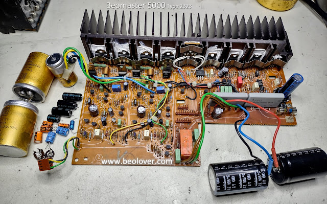
The restoration of the Beomaster 5000 (Type 2323) requires replacing quite a lot of parts.
It is nice that Bang & Olufsen engineered this receiver so it is easy to get to the boards but there are a lot of electrolytic capacitors that have to be replaced.
The circuit boards on these receivers also have very delicate traces. It is difficult to desolder many of the capacitors without incurring some lifted solder pads. In those cases I beef up the connections between the parts with some added jumper wires.
Here are the before and after photos of the circuit board restoration on this Beomaster 5000 unit.
PCB 1 : AM/FM board
Before
After
PCB 2 : Output Amplifier and Power Supply board
Before
After
Along with the capacitors I replaced the left and right channel no-load current adjustment trimmers.
I also replaced the power relay.
PCB 3 : Preamplifier board
Before
After
This board had quite a few non-polar type electrolytic capacitors.
The preamplifier board also had a relay (for muting the speakers) that I replaced.
PCB 4 : Microcomputer board
This board had several axial type capacitors and it had a 3V Lithium battery that I replaced.
PCB 6 : Cooling fan regulation board
Before
After
PCB 9 : Remote control board
Before
After
Now that the old parts that needed replacing are all replaced with new parts I can begin re-installing the circuit boards and prepare the Beomaster 5000 for some bench testing.


No comments:
Post a Comment
Comments and suggestions are welcome!