As I work my way through the long task of rebuilding the front panel switches of this Beomaster 4400 I was able to take some time to get the old electrolytic capacitors replaced on circuit boards PCB 2, PCB 3, PCB 4 and PCB 5.
I like to measure all of the capacitors I remove to make a note of how bad the old capacitors have gotten to. In the case of this Beomaster 4400 almost all of the electrolytic capacitors were way out of tolerance.
Many were fifty percent or more from their rated value. Most electronic designs like this Beomaster 4400 allow twenty percent on their electrolytic capacitors so this Beomaster was in dire need of the upgrade.
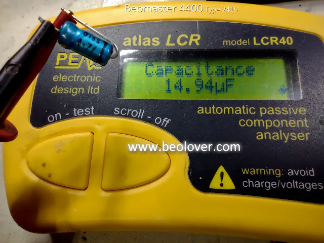
Here are a couple examples of the worst capacitors that I came across and replaced.
A 4.7uF capacitor
A 1.0uF capacitor
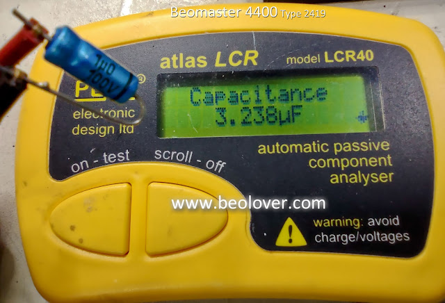
Both of those were three times their rated value!
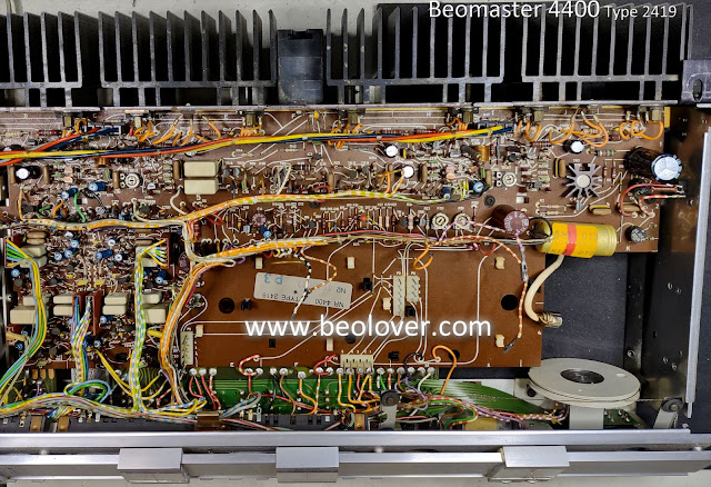
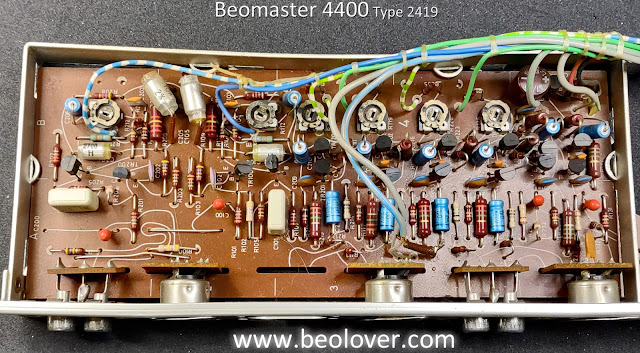
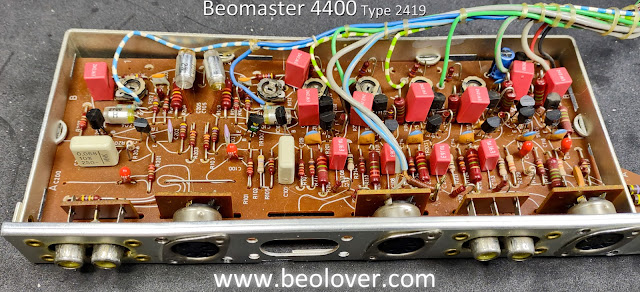
Here are the before and after pictures of the PCB 5 (AF Amplifier, Power Supply, Muting and Silent Tuning) capacitor replacements.
Before
After
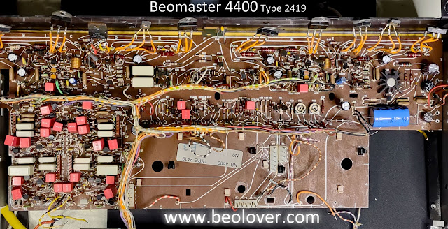
Note that I still haven't installed the new trimmer resistors for the left and right channel no-load current biasing in the output amplifiers. I will do that after the capacitor replacements.
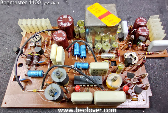
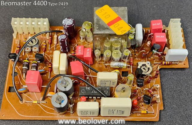
Here are the before and after capacitor replacement photos of PCB 4 (Pre-Amplifier)
Before
After
Note that I kept the four tantalum capacitors on the Pre-Amplifier board. I de-soldered them for testing and all four measured almost right on their rated value so I kept them. The other, electrolytic capacitors were all way out of tolerance as the ones I replaced on PCB 5.
Next is PCB 3 (Stereo Decoder and Indicator Circuit Board).
It also has some tantalum capacitors (two) that I kept because they measure good.
Before
After
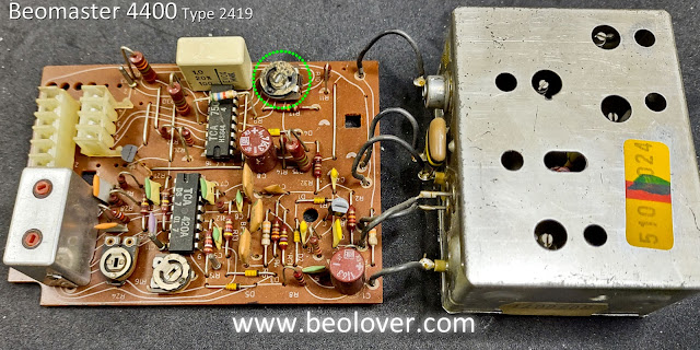
Finally, PCB 2 (IF-Section Circuit Board). PCB 1 (Front End) has one tantalum 10uF, 10V capacitor inside the metal box. It measured good so it won't be replaced.
PCB 2 only had two electrolytic capacitors to replace (a 4.7uF and a 1.0uF capacitor).
I did discover a bad trimmer resistor and will replace it when I go over the circuit boards again to check the trimmers.
Here are the before and after photos of PCB 2
After
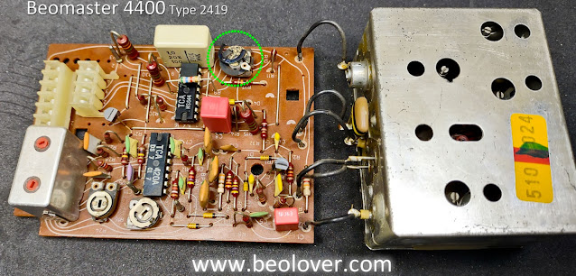
As you can see, trimmer resistor 2R10 has problems and is falling apart.
Now that the capacitor replacement on the circuit boards is complete I will check the condition of the trimmer resistors and replace any that are faulty.
I also still have the two large filter capacitors to replace for the output amplifier rail voltages.
Of course there is still the matter of finishing up the restoration of the control panel switches so I still have quite a bit of work to do on this Beomaster.
No comments:
Post a Comment
Comments and suggestions are welcome!