This post documents the restoration process of a Beogram 4000 that I received a while ago from Berlin. This shows the opened up unit as I received it:
As usual I started out with restoring the carriage section. There was a lot of crusted up lubricant on most moving parts. The previous owner seems to have believed 'more is better' when it comes to lubrication...;-):
I removed all the moving parts of the arm lowering mechanism as well as the rods the carriage travels on and the threaded rod that drives it for cleaning:
This shows the cleaned parts:
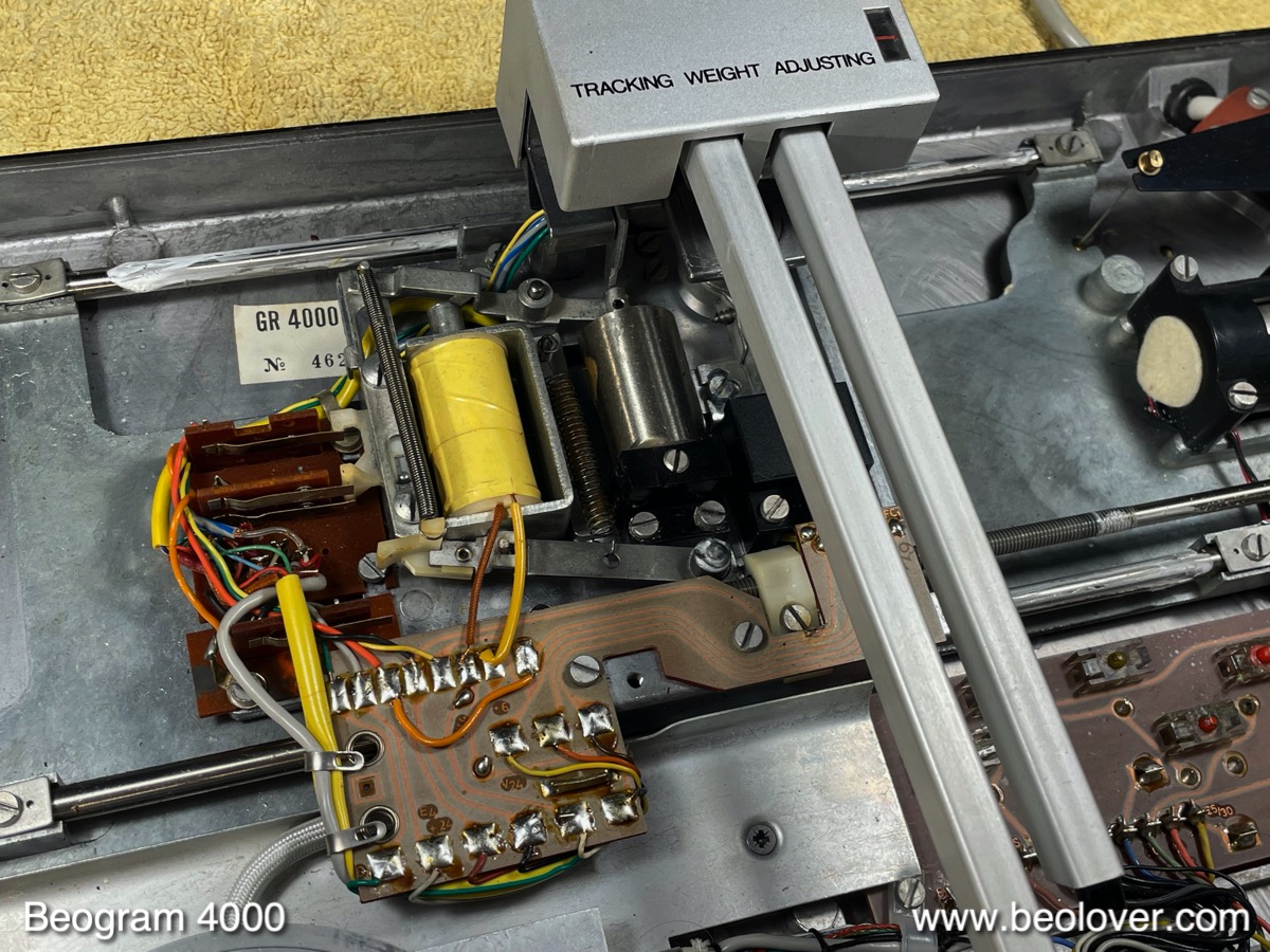
While the carriage is up it is a perfect moment for tending to the solenoid actuated switches, shown here on the left of the yellow solenoid:
I turned the carriage around,
which allows removing the three small boards that hold the switch terminals:
I extracted the terminals for gold plating:
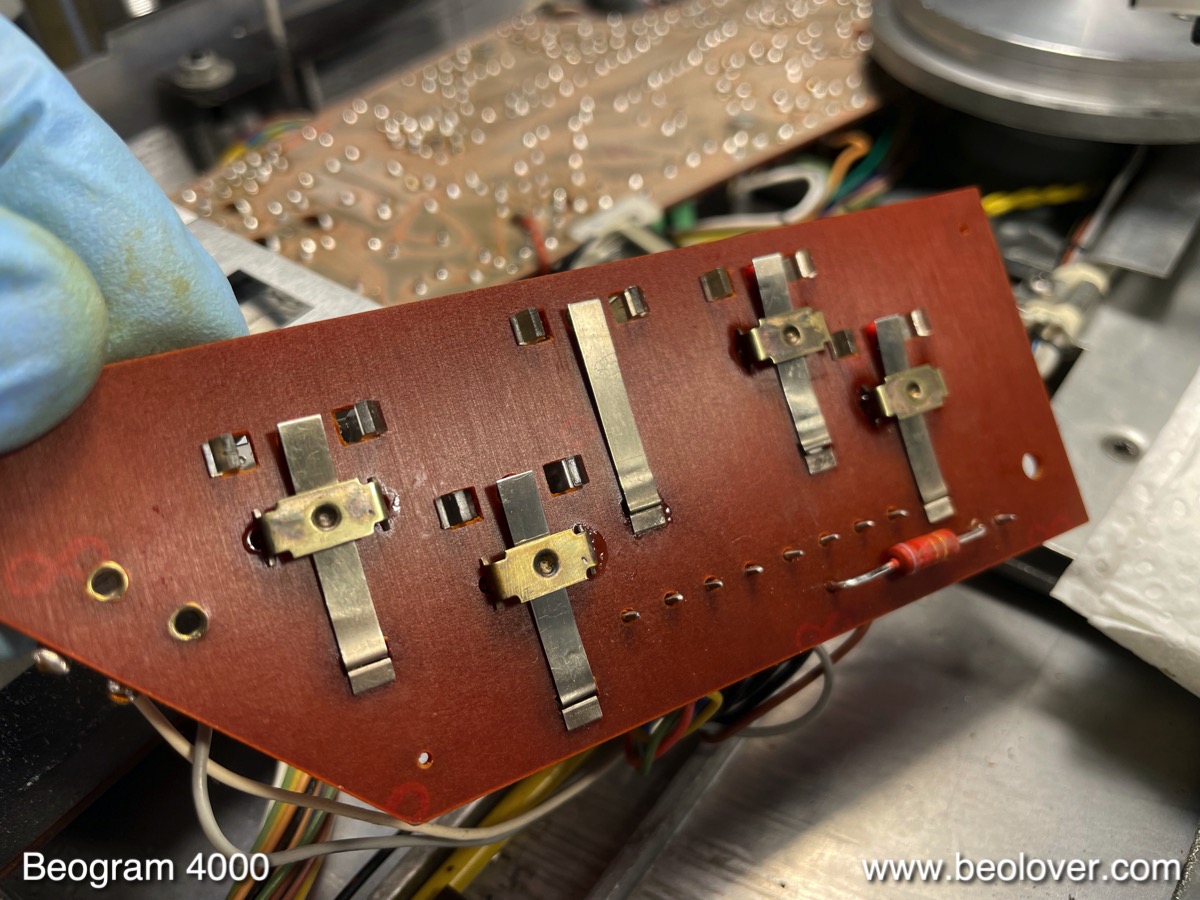
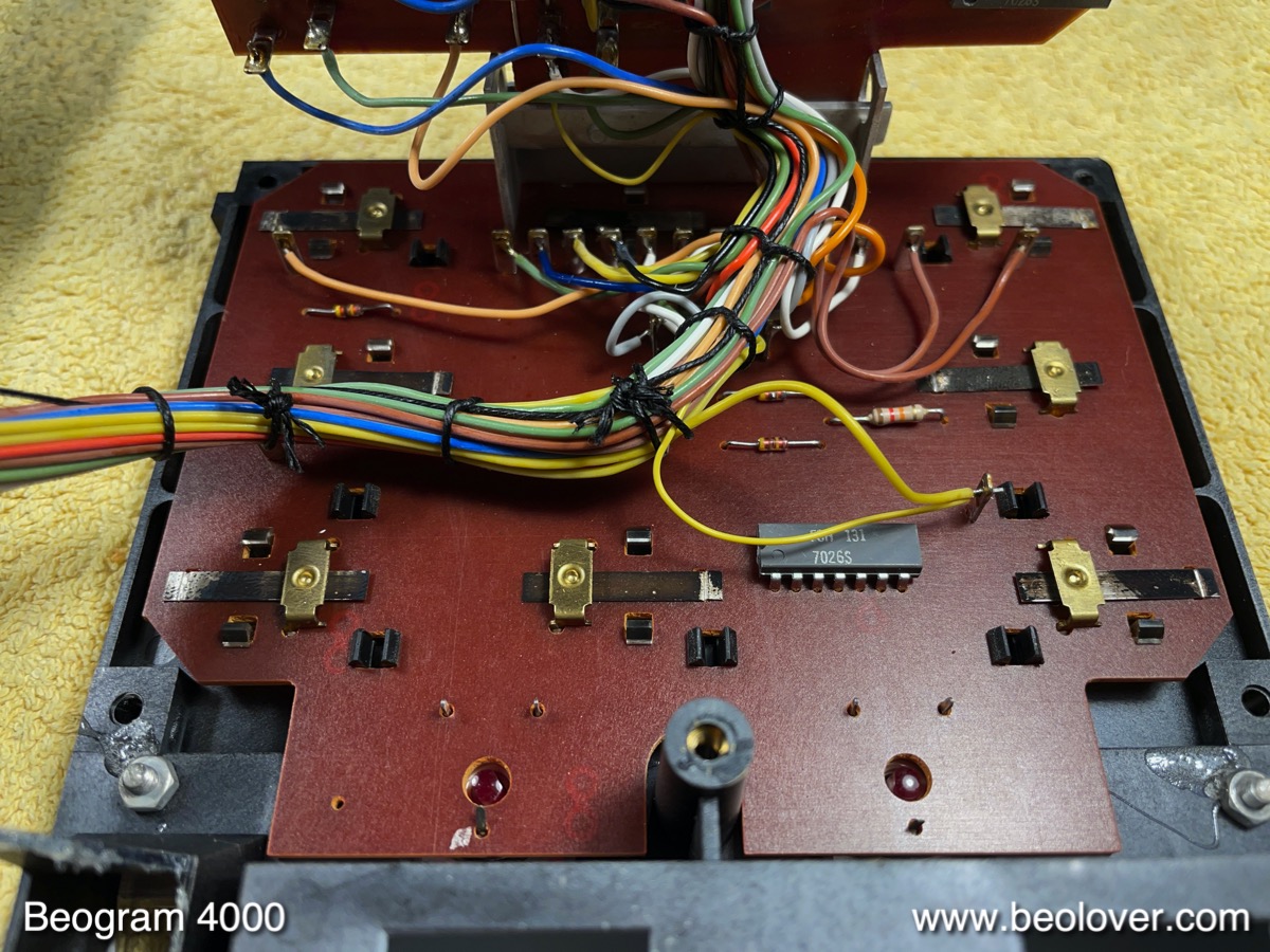
While the carriage is removed, it is also convenient to restore the small PCB that holds the switches that tell the control system where the carriage is located:
As usual these switches were encrusted with old lubricants from previous attempts to keep the deck functional. I unbolted the board and turned it around, revealing the terminals and the solenoid resistor.
I removed the switch terminals. I usually gold plate them together with the solenoid switch terminals:
This shows this first batch of switch components plated with Ni (for adhesion) and then a gold-cobalt alloy (the standard for electronic contact plating since the alloy is harder than pure gold):
Then I re-installed the terminals:
Beolovely! This shows the three solenoid switch boards back on the carriage PCB:
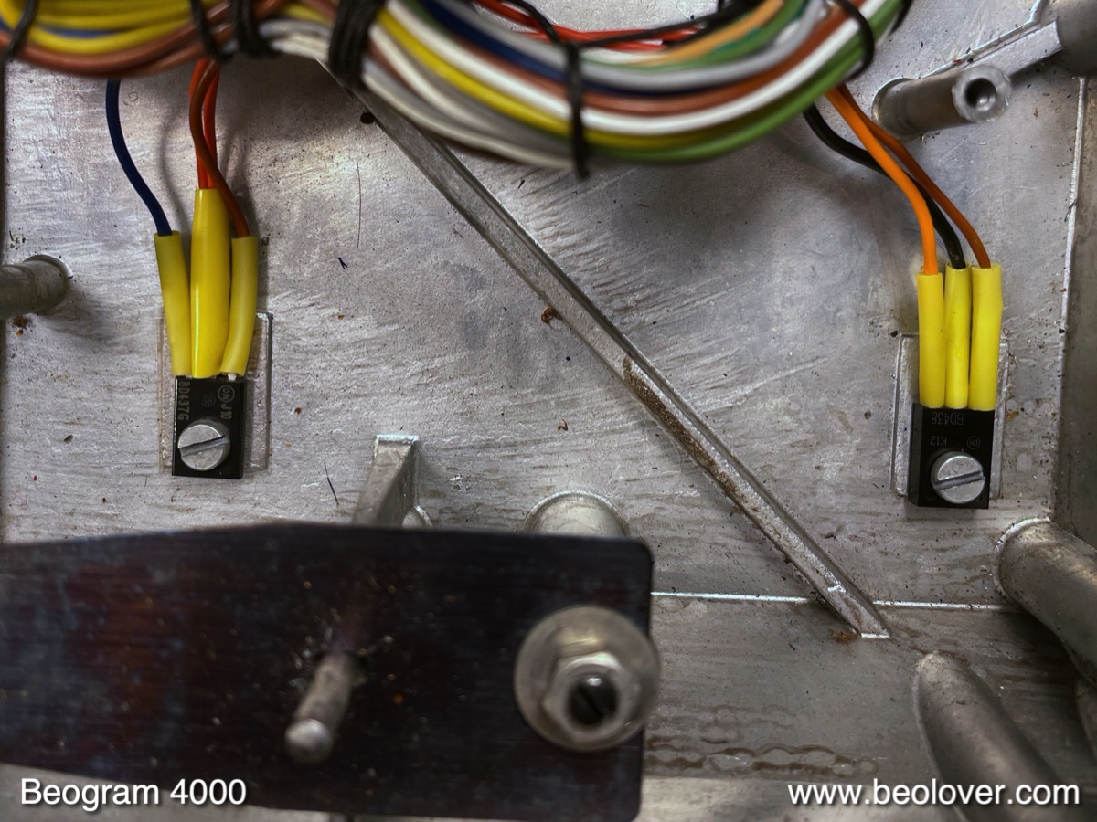
While the carriage is removed, it is also the perfect moment to get to the solenoid transistor:
This transistor often fails, so I replace it preventatively with a TIP41C that has a higher voltage rating to help it cope with driving an inductive load:
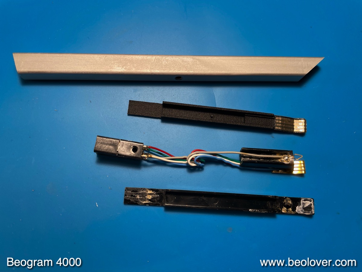
Another item to do while the carriage is up, is the replacement of the MMC cartridge mount in the tonearm. I replace all of them since the plastic B&O used for the 4000 has become brittle after 50 years, which often results in broken off tabs while replacing cartridges on the arm. This is a special issue in 4000s, and it seems B&O realized this issue quickly, and the MMC mounts used in later 4002 and 4004 designs were made from a different, more resilient material.
I removed the arm, and it turned out that this is an early version setup, where the arm connects elegantly via spring loaded terminals to a small PCB that sticks from the back into the arm:
This shows the removed arm taken apart together with the 3D printed Beolover MMC mount replacement part (right next to the arm)
I installed the part:
It is important to make sure that the new mount is installed in a way that the cartridges can be stuck on far enough to sit flush with the aluminum profile of the arm:
Then I replaced the light bulb in the tracking sensor assembly with an LED. This shows the original bulb housing:
I replace them with an LED based assembly shown here on the left in comparison with the original bulb setup:
This shows the component installed:
After this I focused on the restoration of the keypad cluster. I extracted it and opened it up into service position:
As usual the small mirror that reflects the light coming from the strobe pattern under the platter into the small window in the keypad had come off:
This shows the badly oxidized switch terminals that are connected to the keypad:
I removed them for gold plating:
And this shows them restored with their new gold coats:
I re-implanted them:
Beo-golden! The next step was to replace the light bulbs in the keypad cluster with Beolover LED assemblies:
Then I glued the mirror back on:
This concluded the work on the keypad assembly. I moved on to restoring the electronic circuits. This shows the main PCB flipped up:
I replaced all electrolytic capacitors, the transistors of the H-bridge and the AC motor driver (they have a history of going out of business), and the components of the RPM control circuit (relay and trimmers). I also replaced the transistor that amplifies the sensor signal (they often loose part of their gain, which is important for detecting the absence of records properly) and upgraded its bias resistor with a trimmer so one can adjust the working point of the transistor properly. This shows the board after these interventions:
There are only two electrolytic capacitors on the power supply board that need to be replaced (the two small brown units with a white dot in the lower right quadrant):
This shows them replaced with two modern capacitors:
While the main PCB was up, I also replaced the two power transistors of the push-pull stage of the AC motor. This shows the original units bolted to the enclosure for thermal relief:
And here their modern replacements:
The next 'station' of this restoration was the AC-motor and reservoir/motor capacitor section. This shows the original setup with the early version AC motor:
I removed everything and cleaned all traces of leakage from the old capacitor cans (the residue can usually be removed by soaking the it with some isopropyl alcohol for ~1hr):
I decided to abstain from opening up the early-version motor since it seems to run very well, and it is held together by easy to break off metal tabs. I did not want to jeopardize this project by crossing a point of no return without having a replacement motor on hand. Therefore I only installed a new Beolover capacitor assembly shown here:
One more item was to do on the carriage, but it is best done after the carriage has been installed again. It is the lubrication of the pivot point that holds the linkage between damper and tonearm assembly, shown in this picture:
I removed the sensor arm to get to the linkage:
After cleaning and lubricating the pivot pin I put everything back together:
Before re-installing the keypad cluster, it is best to replace the cracked plinth guidance washers. One of them is located under the keypad.... I replace them with 3D printed nylon replicas. One of them is printed black. It is for the center front position, where white washers can be seen through the gap between plinth and aluminum panel.
This shows a white one installed:
And the black one up front:
The next step was replacing the last incandescent bulb located in the sensor arm. Since this is an early version 4000, the sensor bulb also plugs into a spring loaded socket, and can easily be removed without worrying about ripping off some fragile wires. This shows the removed bulb and sensor compartment, still with the original bulb installed. The replacement assembly composed of LED circuit and positioning aid are shown below it:
This shows the installed LED board together with the removed bulb:
Before testing the rebuilt setup I needed to adjust the bias resistor to get around 1.8V at the collector of TR14, which amplifies the sensor signal:
After adjusting the trimer, I installed it on the component side. Then I put the platter on and measured the sensor response to an empty spinning platter:
A very nice signal with a 3.2V pp amplitude. This shows the sensor arm in action:
The special warm white LED installed on the LED board makes sure that the red B&O logo is appropriately illuminated from the back.
I also adjusted the motor voltage to yield a nice strong sine wave at the motor capacitor. This shows the signal for 33 RPM at 42 Hz:
Next I added a switch to the output terminal that allows connecting signal and system grounds. Common grounding the two can be helpful if there is a persistent hum when connecting the Beogram to an amp. This shows the switch soldered between the signal and system ground terminals:
On to the adjustments. The first step is always to adjust the floating chassis making sure platter and arms are aligned with each other. Once that has been established it is time to calibrate the tracking weight and adjusting the arm lowering limit.
I usually replace the flimsy circlip that holds the counterweight adjustment screw in place with a M3 nut. This allows locking the weight calibration into place, which helps keeping the calibration accurate during shipment. This shows the nut installed:
Then I calibrated the tracking weight scale to make sure it is reflecting the correct weight in the 1-1.2g range. These scales are notorious for being inaccurate, i.e. it is a good idea to get a small tracking weight scale and simply adjust the weight with it, while ignoring the scale on the adjustment mechanism:
The next step was adjusting the arm lowering limit. This adjustment makes sure that the needle does not hit the ribs should ever the arm get dropped onto an empty platter (due to a malfunction of the record detection circuitry):
The next step was adjusting the tracking feedback:
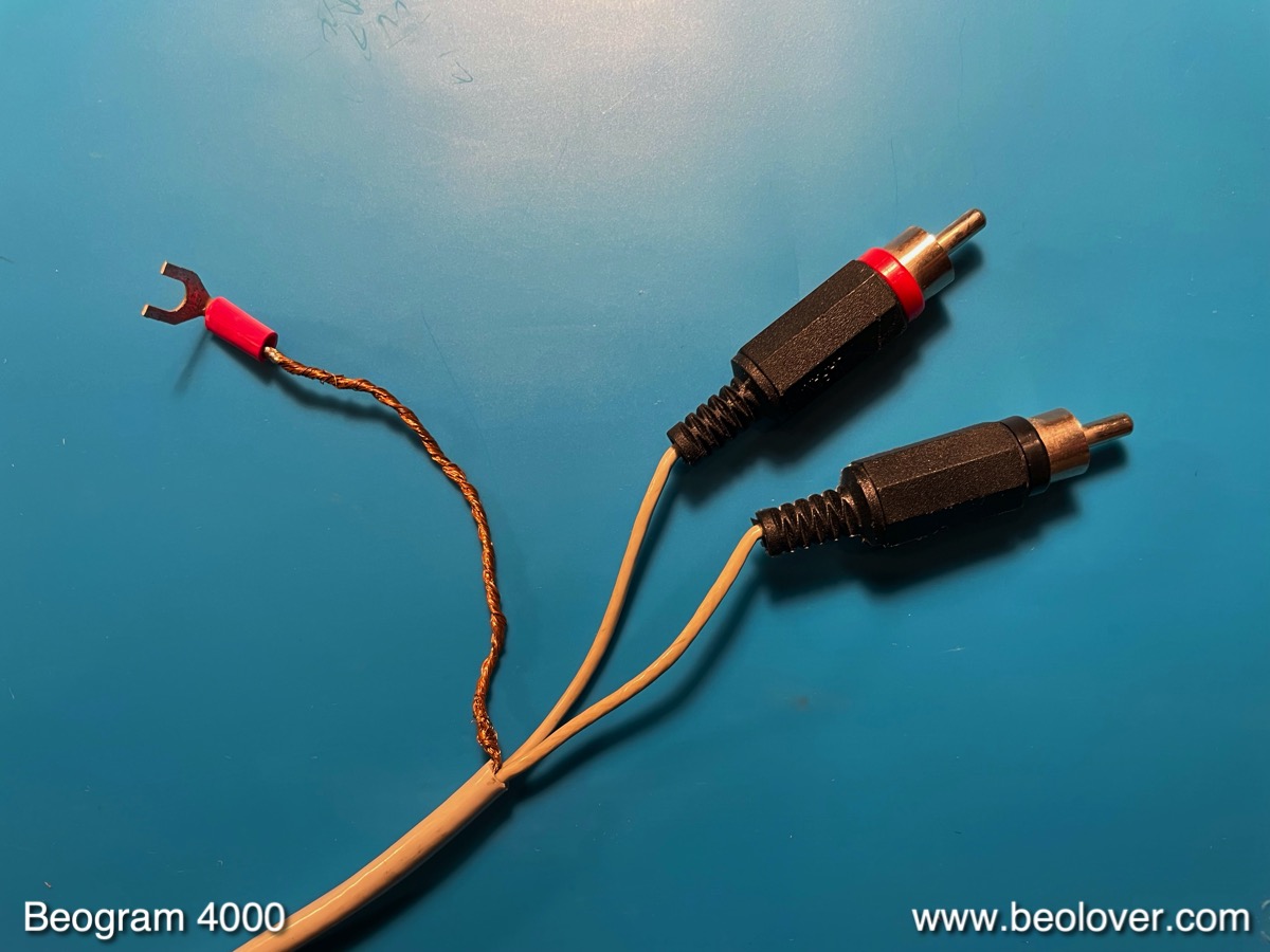
Finally, I replaced the makeshift RCA conversion of the output cable
back to a proper DIN5 with gold plated pins:
And then it was time to do a RPM stability measurement to make sure the motor control was working properly. I did this with an experimental setup I am currently working on since I had forgotten to bring my BeoloverRPM device that I usually use for this measurement. This shows the experimental setup in action:
This is the curve I measured:

This is as good as it gets. But not surprising since the Beogram 4000 has a synchronous AC platter motor, which usually have excellent RPM stability.
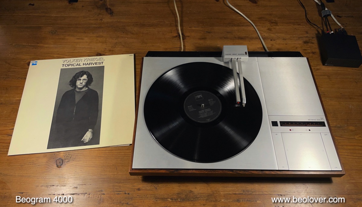
This happy result meant it was finally time for a test spin with a nice record! I selected Volker Kriegel: "Topical Harvest" from my Dad's record cabinet. A lovely MPS release from 1976, bought in 1977 when it had been reissued the first time! I remember listening to it on a Saba HIFI Studio 8740 with a Dual 1225 turntable when I was a kid. Now it still played wonderfully, but on a much more beautiful record player!...;-).
Very Beolovely! Soon it will be time to send this Beogram 4000 back to its owner in Berlin!