Featured Post

Beolover SyncDrive: DC Platter Motor Replacement for Beogram 4002 and 4004 (Type 551x and 552x)

Late Beogram 4002 and the 4004 (Types 551x and 552x), which have DC platter motors instead of the earlier synchronous AC motors usually suff...

Showing posts with label circuit boards. Show all posts

Saturday, April 23, 2022

Beomaster 4400 Type 2419: Front Panel Wiring & Reassembly

The last post left off with the Beomaster 4400 ready to have its front panel wired back up to the rest of the Beomaster electronics.

Part of the wiring from the Beomaster 4400 front panel components (switch assembly, PCB 6 and PCB 9) is accomplished with wire harnesses and connectors. Unfortunately there are a few wire connections that B&O left as hard wired. That is what makes the front panel disassembly such a chore.

The task becomes even more difficult if it is necessary to disassemble the switches...like I did in this restoration. That is because wires from the harnesses must be desoldered along with the removal of PCB 6 and PCB 9 to get access to the switches.

Now it is time to put everything back.

One wire re-connection task that does not have a harness or connector is for the speaker selection switches.  The Beomaster 4400 speaker connectors are on the rear panel of the Beomaster cabinet while the speaker select switches are on the front panel.  That is how they should be of course but it means the wiring must travel to and from the switches and connectors.

Here is a photo of the speaker wiring (including the headphone jack wires) and the switch panel board (PCB 9).


Here is a diagram that shows how the wires need to be connection on PCB 9.


This is a photo of the speaker and headphone jack before connecting the wires.


Here is everything wired back up.


Continuing down the front panel from the speaker wiring towards the FM tuning dial assembly I connected the various wire harnesses and individual board to board wires.

This wire harness connects the front panel tone control switches (Mono, Linear, Loudness, Lo Filter, Hi Filter) to the main board tone controls circuitry.
The photo shows the harness before and after being re-connected.


The next series of photos show details of the remaining loose wires that had to be connected.
That includes the wires that are part of the main, PCB 5 harness with the front panel lamps.


Next, I installed the harness with the slider controls (Volume, Bass, Treble, Balance).


Last, I re-installed the main FM tuning assembly.


Here is the Beomaster 4400 with the front panel assembly back in place.


In the next post I will re-mount the output amplifier transistors to the heatsinks, re-install the other PCBs (FM boards and preamplifier board) and re-connect the wires for powering up the Beomaster 4400. 

Sunday, April 3, 2022

Beomaster 4400 Type 2419: Continuing the Reassembly of the front panel switches

Continuing on from the previous post with the reassembly of the Beomaster 4400 front panel switches, I will also continue showing the differences in the switch panel components between early serial number units and later serial number units.

I did look up the B&O service manual addendum on the change with the switch panel.
According to that documentation the "early serial number" switch assemblies are for Beomaster 4400 serial numbers prior to SN 1524001.  Units with serial numbers 1524001 and on have the new switch assemblies.

That bears out on the Beomaster 4400 units I have seen.  The serial number for the Beomaster 4400 of this project is 1510043.

Here are some photos of the Beomaster 4400 front panel for both versions side by side.

From the front the difference is in the way the slider controls mount to the front panel.
The later serial number panel mounted the controls with screws from the front while the early serial number panel used metal spring clips. For that reason the early serial number front panels included a narrow mounting bracket for the slider controls to rest on.
The metal button panel frame that the switch assembly mounts to also changed due to the different style of switch actuators.


This picture shows the type of slider controls the Beomaster 4400 uses for the early serial number and later serial number units.


On two the circuit boards and wiring.
Both types of front panels have a small LED glued in place for the Stereo Indicator.
It is difficult to detach that LED assembly when disassembling the front panel so I started cutting the two wires that connect to the LED assembly.  When reassembling the panel I install a small 2-pin connector for the cut wires. That makes it a little easier in servicing the front panel.


The switch assembly is mounted to the front panel on a metal, button panel frame. 
It is secured with two screws.
The important thing here is to make sure all of the plastic switch actuators are pressed against their respective push buttons.


Now that the switch assembly is secured onto the front panel it is a good idea to double-check the mechanical operation of the switches again.


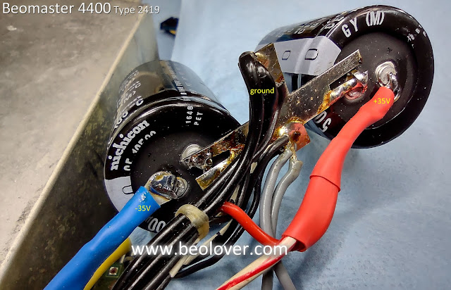
While I was working on the front panel assembly I took a little detour to replace the two 10,000uF electrolytic capacitors for the ±35 VDC output amplifier rails.  These are the two capacitors that are mounted on a bracket just to the side of PCB 5.


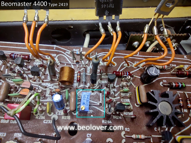
I also took a little time to install the two 100Ω trimmer resistors for the no-load current adjustment of the output amplifier. On those two trimmers I always go with multi-turn trimmers as they are easier to fine tune.

Here is the left channel trimmer.


Here is the right channel trimmer.


Returning to the reassembly of the front panel I decided to prepare the new incandescent lamps in the front panel wire harness.

Three of the five original lamps still worked but since I have to replace two I am going ahead and replacing all five with proper lamps from Martin's Beoparts store.

Here are the original lamps removed.


Here are the new lamps installed.


The next step of the front panel reassembly is to re-attach the circuit boards that mount to the switch assembly.  They are how the switches electrically connect to the Beomaster.

First is the PCB 6, 2-piece board.  
It has a normal, rigid PCB part and a flexible part to connect to the FM tuner preset dials.


The next PCB to attach to the switch assembly is PCB 9.


Here is a picture of the circuit boards reattached to the switch panel.


The front panel reassembly has gone smoothly so far.  
It is at the point where the wire harnesses get reattached.
In some cases that just means plugging in some connectors but unfortunately for me it also means quite a few loose wires that do not have a connector.  
That is the reason you have to take a lot of photos during the de-soldering of those wires when the front panel is being disassembled. 
I have those of course and my task for next time is to gather all of that information and carefully solder all of the individual, loose wires back in place.