This post discusses the restoration of a Beogram 4004 (Type 5526) that I recently received from a customer in California. The initial assessment of this deck is posted here.
This shows the Beogram in 'service position' with the aluminum panels removed:

This 4004 is in pretty good cosmetic condition and below deck it was in original condition, too, always the best starting point for a restoration.
As usual with a DC platter motor Beogram, I started with the motor since the oil-infusion of the bearings takes several days. This shows the motor as extracted:

I took it apart to get to the bearings:

They are the two small donuts on the black pad up front. I immersed them in motor oil and pulled a vacuum. Immediately strong bubbling started:

The bubbling represents air that is drawn from the bearing by the vacuum. While the air leaves the pores of the Oilite bearing material, oil refills the pores. This oil serves as lubricant for the shaft, and is continuously drawn from the bearing material as the shaft rotates. Eventually the bearing is 'empty' and needs to be refilled.
While the oil diffusion took its course I focused on the other tasks of the restoration.
First I rebuilt the carriage. The arm lowering and carriage transport mechanisms usually need a good cleaning from hardened old lubricants, and subsequent re-lubrication with modern synthetic lubricants. This shows the arm lowering mechanism in place:

I removed all the moving parts:


and cleaned them in an ultrasonic cleaner:

Nice and shiny again! Beolovely! The next step was re-assembly. As usual, I put a new rubber gasket into the damper:

This is important to ensure a consistent arm lowering experience. The old original rubber rings are usually hardened and this can cause sudden changes in the arm lowering speed. This shows everything back in place:

I also installed a new machined aluminum carriage pulley. The original one was cracked at the set screw:

There is one more moving part in the arm lowering assembly that needs to be cleaned and lubricated: The connecting linkage between damper and tonearm. It has its pivot point located on the sensor arm base. You can see the linkage here. It is the part that sticks out from the V-cut on the connector that is bolted to the end of the arm weight assembly:

To get to the linkage the sensor arm needs to be removed. This shows it with the linkage already removed:

As in most cases the small copper plate that helps the arm move laterally when in up position also was loose. A light tug with my tweezers removed it. I epoxied it back into place:

After bolting the sensor arm back in place I started working on the circuit boards. The main PCB was first. This board has two power transistors mounted on the solder side. This shows one of them, IC4, a Darlington. Originally IC4 is usually a TIP125:

I normally replace IC4 with a stronger TIP107 type. This IC controls the solenoid and therefore sees some 'action'. So a bit more current capability may help longevity. This shows the new TIP107 in place:

Once the power transistors have been replaced it is time to remove the board and replace the remaining power transistors, all electrolytic capacitors, the sensor transistor, which often is out of spec, and the RPM relay and trimmers. This shows the board in original condition:

Here a close up of the RPM section:

And with exchanged components:

This shows the RPM section updated with a modern encapsulated relay and new 25-turn trimmers for RPM adjustment:

After completing the main PCB, I did the output PCB, which in the 4004 also contains circuitry that enables remote control of the deck via a Beomaster 2400. This shows the board in its original condition:

This is a close up of the output section consisting of the output relay and the small circuit that controls the relay delay after the arm has been lowered:

I replaced all the electrolytic capacitors and the relay:

I also installed a switch (red) that allows connecting system and signal grounds:

Connecting signal and system grounds often quenches hum issues, especially if a Beogram is used with an RCA input amplifier.
Now it was time to replace the four incandescent light bulbs in the deck. Two of them are in the RPM adjustment panel above the keypad. This shows the panel removed with the two bulb covers removed:

This shows the removed bulbs together with the Beolover LED assemblies which will replace the bulbs:

I soldered the LED boards into place:

They solder directly to the bulb terminals:

They do not obstruct the bulb covers, which can be put into place after the exchange:

The third bulb is in the sensor arm. It serves to illuminate the platter so the absence of a record can be detected from the reflected light 'pattern'. This shows the small sensor compartment pulled out of the sensor arm together with the LED replacement assembly:

I installed the LED board:

Here you can see the LED in action. It uses a warm white LED which produces enough red photos that the B&O logo is illuminated properly:

The final, fourth, LED is in the tracking sensor assembly under the arms. This shows the original setup in place:

I removed the bulb housing, which revealed the aperture that is used for the tracking feedback mechanism:

I installed the Beolover tracking sensor LED assembly:

The small white box on top is a trimmer that allows adjusting the light intensity of the LED, which can be helpful for fine-tuning the tracking response.
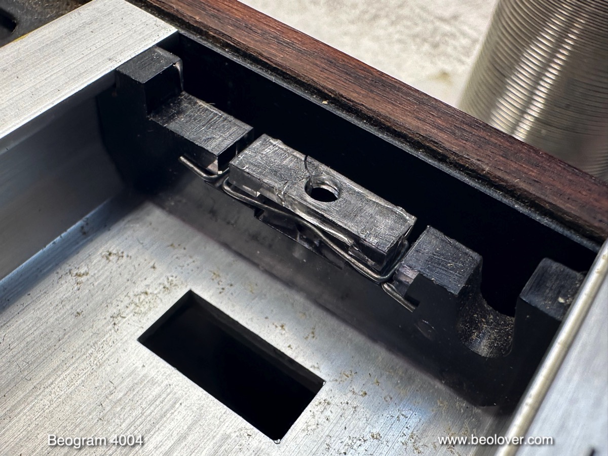
With most of the components removed from the enclosure, it was time to focus on the transport lock bushings, which were completely degraded in this 4004. Here you see one of the locks where the bushing was completely gone:

I removed the floating chassis to clean out the enclosure. When the bushings degrade they create a nice mess with a lot of debris distributed around the enclosure:

This can cause impediments for the motion of the floating chassis since there is only limited space under it. I vacuumed all the debris out of the enclosure:

An then it was time to re-assemble everything. I installed a new reservoir capacitor:

Then I installed new Beolover transport lock bushings. They come in two halves, which makes installation very easy:

Simply insert one half from the bottom

And the other half from the top. Then the lock screws can be installed:

This shows a completely re-assembled lock:

When I re-installed the keypad assembly, I noticed that the two plexiglass spring assemblies that hold the RPM panel down were cracked:

This often happens and when it does, the RPM panel does not stay down in place anymore. Luckily, there are new replacements available from the Beoparts-shop in Denmark. All one has to do is transferring the metal spring clips:


Beolovely! Another issue with this deck was its bad condition power cord. It was very dirty

and also had some damage. Almost looked like some audiophile rodents had a go at it!...;-):

My customer decided that he could be happy with a shortened cable and so I removed it and cut off the damaged part, and re-installed it. The first step for such an operation is to take out the line voltage switch box (which is a placeholder in the 5526 US version of the 4004). It is held in place by two screws accessible from the bottom of the enclosure:

Once the box is open the in and out cabling becomes visible:

The wiring connects to the fuse holders in the top part of the box:

As so often, when I removed the fuses one of them came apart:

It seems fuses also deteriorate with age. The incoming cable is soldered to one end of the fuse clips. After de-soldering the wires they can be pulled out from the box:

I pulled the cable out, cut the damaged part off, cleaned it thoroughly and installed it again:

Now it was time to do the adjustments. First I adjusted the collector voltage of TR3 to the prescribed 4V using my newly installed 5MOhm trimmer that replaced its fixed 1MOhm biasing resistor:

Using a trimmer instead of the fixed resistor allows compensating for the gain of the particular transistor that is installed. Even if transistors have the same type and come from the same batch, their gains are varying over a specified range, i.e. biasing may need to be adapted if there is no feedback like in this case. After doing any work on the record detection system it is a good idea to measure the sensor response over a spinning empty platter to see if the signal is strong enough to reliably disable arm lowering if there is no record on the platter. This Beogram passed with flying colors producing a strong 7.8V peak to peak signal:

Each trough in the signal corresponds to a passing platter rib as the platter spins under the sensor.
After this I did all the necessary adjustments to level the platter, get the correct arms to platter distance and make the platter flush with the surrounding aluminum plates. This process can sometimes be tricky and repeat adjustments may be needed until a perfect alignment is achieved by iteration.
Once these adjustments are done the arm lowering limit can be set:

It needs to make sure that the lower parts of the ribs are missed by the tip if the record detection mechanism would ever fail and allow the arm to be dropped on an empty spinning platter.
Next I calibrated the tracking force by adjusting the counterweight on the tonearm. I usually also replace the flimsy retaining washer that B&O used to hold the adjustment screw in place with a nut. This allows securing the calibration in place to survive the rigors of shipping:

I usually calibrate the weight adjustment wheel in a way that it is accurate around the 1.2g setting:

In the meantime the platter motor bearings had completed their oil infusion process. I extracted them from the oil and re-assembled the motor. Then it was time for a 24 hrs RPM stability test with the BeoloverRPM device:

It allows logging the RPM over extended periods of time in 10s intervals. This is the curve I measured after about 24 hrs:

This is pretty much as good as it gets with Beogram DC platter motors. Since they are controlled by an analog feedback system there is some small RPM variation over time due to temperature changes etc...The small spikes should go away with time as the re-set bearings get polished by the shaft.
Before it was finally time for a first test spin I replaced the 'beautifully' corroded original convertible DIN7 plug

with a new all-metal DIN5 with gold plated contact terminals:

And then it was finally time to sit back and enjoy a first record on this beautiful Beogram 4004!
I selected "The Summer Knows", a beautiful record from 1977 by Art Farmer (Inner City Records 6004)
Of course this vintage record was cleaned thoroughly with a CleanerVinyl ProXL ultrasonic record cleaner. This restored this mint looking record to its original glory. A perfect match for this perfectly performing Beogram 4004!:

I will play this deck some more to make sure that there are no intermittent issues. Once the Beoparts Shop in Denmark will be resupplied with reproduction hoods, this deck will also receive a new hood to complete its pristine almost like-new looks! Beolovely!
No comments:
Post a Comment
Comments and suggestions are welcome!