This post discusses the restoration of a Beogram 4004 (Type 5526) that I recently received from a customer in Maryland. The initial assessment of this deck is posted here.
This shows the unit with the aluminum panels removed:

As usual, I started out with the DC platter motor. They usually need oil infusion of their dry bearings. This shows the motor after I extracted it:

I disassembled it to get to the bearings:

The bearings are the small donuts on the black pad. I immersed them in motor oil and pulled a vacuum. Immediately, strong bubbling started:

This bubbling is indicative of air leaving the pores of the Oilite bearing material, making room for fresh oil. This process usually takes about 2-3 days. When the bubbling stops the pores are replenished with oil.
While this was going on, I worked on the other restoration tasks.
First I focused on the carriage. It carries the arm lowering mechanism, which usually needs cleaning and re-lubrication since the decades-old lubricants are often hardened, impeding the motion of the mechanism. This shows the arm lowering assembly consisting of solenoid, damper and linkages:

I removed all the moving parts as well as the rods on which the carriage travels and the spindle that drives it:

This shows the carriage with the parts removed:

I put everything into an ultrasonic cleaner for an hour, which removed all the old lubricants and made everything nice and shiny:

Then I started re-assembling everything. An important aspect is replacing the damper gasket, which stops the air flow through the plunger during arm lowering. The original gaskets are often hardened, and that can cause unwanted inconsistencies of the arm lowering speed. This shows the new gasket in place:

There is one more linkage that connects the damper plunger with the arm. It is part of the sensor arm assembly. Here you can see it from the side. It presses down the arm lever via the V-shaped cutout on this lever:

I removed the sensor arm to get the linkage out:

As usual the small copper plate that helps the arm move laterally when up came off:

It is only attached with some usually degraded double sided tape. I removed the tape remnants and glued it back into place with epoxy:

After re-assembling everything I focused on the tracking sensor light bulb, which is in the black housing directly under the arms. This shows the original setup:

I usually replace it with a Beolover LED based replacement assembly. This shows the original bulb and the LED part in comparison:

The LED is located at the same position as the original bulb filament. This shows the LED part implanted:

The small white 'box' on the implant is a trimmer that allows tuning the LED intensity. This can be helpful when calibrating the tracking feedback. The final task was to replace the cracked original plastic carriage pulley

with a nice new machined aluminum pulley and a new belt:

And this concluded the rebuilding of the carriage:

Next came the main circuit board. I usually replace all the electrolytic capacitors, all power transistors, the RPM adjustment trimmers and relay and the sensor arm transistor and biasing resistor. It is best to start with the power transistors that are mounted on the solder side of the board. They can most easily be replaced while the board is still bolted it. This shows the original IC1 that is responsible for regulating the 21V power rail. It is usually a TIP120:

I replaced it with a stronger TIP102. Note that these modern devices need a 100nF capacitor to GND at their output to quench some strange high frequency oscillations. Not sure why these oscillations occur, but the 100nF cap does address the issue:

After replacing IC4, it was time to take out the board:

This shows a detail shot of the 'RPM section' with the RPM trimmers and the National RPM relay:

I did all the replacements:

This shows the rebuilt RPM section with modern encapsulated 25 turn trimmers for the RPM adjustment and the Beolover relay replacement that fits into the foot print of the original National relay:

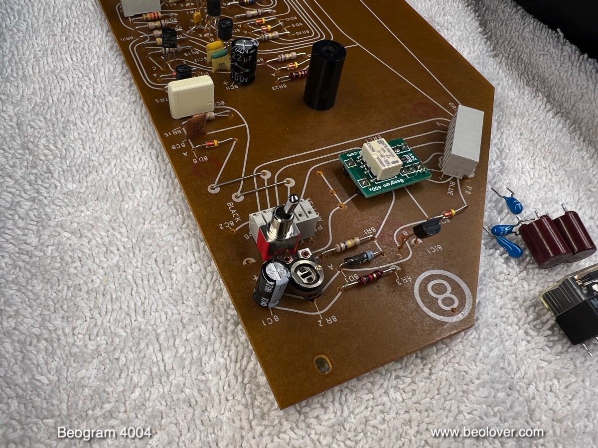
Next came the output board, which in the 4004 is comprised of two circuits: 1) on the right the output circuit that consists of the output relay and the circuitry that determines its time constant. And on the left 2) the remote control receiver that is able to communicate with a Beomaster 2400 and its remote control:

This shows a detail shot of the output circuit:

I replaced all electrolytic capacitors and the relay:

This shows the output section in more detail. I added a switch (red) that allows connecting signal and system grounds in case there is a hum (especially valuable if the Beogram is to be used with a receiver that has RCA inputs):
After the PCBs, I removed the RPM panel to replace its incandescent light bulbs with LED assemblies. This is important since the LEDs produce less heat, which eliminates sudden RPM changes due to thermally induced movements in the trimmers. This shows the back side of the RPM panel:

Removal of the bulb covers reveals the bulb assemblies:

I removed the bulbs. This shows the extracted bulbs together with their LED replacements:

I soldered the LED boards in. They directly connect to the bulb terminals:

Here is a detail shot of one of them:

After the exchange the bulb covers can be re-installed:

After this step it was time to remove the floating chassis from the enclosure to replace the degraded transport lock bushings. This shows one of the degraded bushings:

This shows the enclosure after removing everything and vacuuming out all the bushing fragments:

Now it was time to install the new transport lock bushings in the floating chassis. The Beolover replacement bushings are printed from a resilient nylon material. Their design is based on two identical halves, that can easily be installed by pushing in one half from the bottom and the other from the top:

This shows the installation process: First the lower half is pushed into the orifice

and then the top half is added:

After repeating this process for the other two locks I reinstalled the chassis. This shows one of the bushings with the lock screw in the center:

I also installed a new reservoir capacitor:

After everything was put together, it was time to adjustment the sensor arm transistor to produce 4V at its collector. This was done with the 5MOhm trimmer that I installed to replace its fixed value 1MOhm biasing resistor:

Then it was time to replace the last incandescent bulb, which is located in the sensor arm. This shows the sensor compartment pulled out, which reveals the bulb. Next to it on the white cloth is the replacement assembly:

I installed the LED board:

This shows the LED in action:

It is a warm white LED, which produces enough red photons to properly illuminate the red B&O logo.
Now it was time for the mechanical adjustments. The first step is always to adjust the platter/arm distance, make sure that the platter is level, and then adjust the floating chassis that the platter is flush with the surrounding aluminum panels. This can be a tedious process that requires a few iterations. Then the remaining adjustments can be made:
First I focused on calibrating the tracking weight. This shows the standard B&O setup of the counterweight adjustment mechanism: The screw that adjusts the weight position is held in place with a circlip and some glue:

I do not particularly like this setup since it can still shift during transport. I usually replace the circlip with a M3 nut that can be tightened:

This makes the calibration resilient to the stresses during shipping. This shows the tracking weight measurement after calibration with the weight dial set to 1.2g:

Another important adjustment is the arm lowering limit. It needs to be set that the needle misses the lower parts of the platter ribs when the arm is lowered. The manual prescribes a 1mm gap:

This ensures that the needle does not get damaged should the arm ever be lowered on an empty platter due to a circuit malfunction. The final adjustment was the tracking feedback:

In the meantime the oil infusion of the bearings had completed. I extracted the bearings from the oil:

Then I re-assembled the motor and installed it in the Beogram for a RPM stability test with my Beolover RPM device:

Aside from precise RPM adjustments, this device allows logging the RPM in 10s intervals over long periods of time. The blue curve in the graph below is what I got after about 24 hrs. Not very beolovely, to say the least. The strong RPM drops after maybe 15 hours are indicative of a failure of at least one of the spark snubbers that are soldered to the rotor.

So I extracted the motor again and took it apart a second time. This shows the rotor from the commutator end:

The yellowish devices are the spark snubbers that are soldered between the pole terminals of the windings. This shows the original snubber after extraction next to their modern replacements:

I soldered the new snubbers between the terminals:

Then I put the motor back into the Beogram and did a second measurement. The red curve resulted after 24 hrs. It appears the new snubbers cured the RPM drop issues.
On to fixing the messy output cable situation. This shows the setup in place when I received the unit. someone 'converted' the original DIN plug to a makeshift RCA setup. Since DIN cables are typically not setup to be used as RCA cables this looked a bit improvised:

I cut the cable off and installed a female DIN7 jack, essentially restoring the original convertible DIN7 configuration:

This basically matches the situation encountered in the later Beogram 8000x series, where they installed a DIN7 jack in the back of the enclosure. The 4004 does not have a suitable cutout that can be used, so the jack has to be mounted on the cable.
Why does the Beogram 4004 need a DIN7 output configuration in the first place? It is the first B&O device that had an integrated control interface, an early Beolink if you will. The 4004 could be controlled from a Beogram 2400, which was able to automatically start the turntable when phono was selected. Also its remote control was able to pause and re-start playback. This was possible by using the additional two pins on the DIN7 as data lines transmitting the remote control signals, while maintaining a standard DIN5 output configuration on the 5 'normal' pins.
Installing a female DIN7 allows connecting to a Beomaster 2400 with a male-to-male DIN7 jumper, or to a standard DIN5 input with a male-to-male DIN5 jumper, or even to RCA inputs by using a standard male DIN5-to-RCA adapter.
This shows the DIN5 variant:

While working on the cable, I noticed that the plexiglass tab that holds the output cable in place inside the Beogram had cracked off from the circuit board mounting tab:

Since this happens fairly frequently due to the weak design of the plexiglass part, there is a Beolover replacement part available. This shows original and new together:

And the new part installed:

The final step was the installation of a Beolover Commander remote control system:

The Commander is the perfect way to preserve the keypad and make sure it does not degrade further. The keypads are coated with a clear coat that wears off over time due to friction and chemical reaction with the oils and fats present on skin. The Commander allows complete control of the deck via a paired Apple Remote control without ever needing to touch the keypad. It also gives the Beogram autorepeat functionality as well as a dynamic scanning function.
And now it was finally time to give this restored Beogram a first spin. I selected one of my favorite albums of all time, "Pharaoh" by Pharaoh Sanders. He recorded this wonderful record in 1977 and then it was not available anymore on vinyl for a long time. And finally 2023 came around and it was finally re-issued in a beautiful box (Luaka Bop 6 80899 8008-2-2) together with a second record containing two really interesting life recordings of the main track 'Harvest Time'. Absolutely awesome! A perfect album to play on this Beogram 4004, which may have been purchased one or two years after this record was first released!
Of course this album was thoroughly cleaned from pressing residues on a CleanerVinyl ProXL ultrasonic record cleaner using a UC-3360 multi-frequency cleaner. Removal of chemical contamination is done best at higher ultrasonic frequencies, i.e. the 120kHz setting of the UC-3360 is perfect for that.
Beautiful!:

The final step was to replace the scratched up hood with a new reproduction hood and aluminum trim. The first step was to remove the hinge assembly from the original hood. For this one needs to access the screws that bolt the hood to the hinges. Usually a fresh razor blade does the trick:


The next steps are bolting the hinge into the new hood and then glueing the strip on. This shows the end result:


Beautiful! I will now play this deck a while longer and if nothing additional comes up it will soon be time to return it to its owner!
No comments:
Post a Comment
Comments and suggestions are welcome!