This post discusses the restoration work performed on a Beogram 4002 (5513) that I recently received from California. My initial assessment of this unit is posted here.
This shows the unit as received with the panels off:

It looked fairly original to me at this point, but closer inspection of the main board revealed some previously made 'repair' attempts (see below).
As usual with DC motor Beograms, I started out with the platter motor. This shows it after extraction:

I disassembled it to get the bearings out for oil infusion under vacuum. The bearings are the two small donuts on the black pad:

This shows the bearings immersed in motor oil after pulling a vacuum:

Vigorous bubbling indicated that these bearings were 'dry', i.e. most of the oil in the porous bearing material had been used up and replaced with air, which the vacuum now drew out. This made room for fresh oil to diffuse into the material.
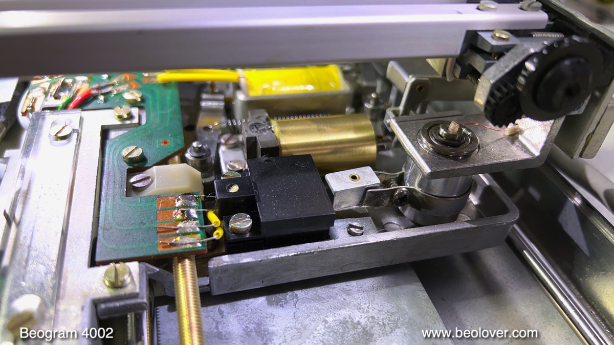
While this process was taking its course I started working on rebuilding the carriage. First I removed all the parts involved with translating the carriage and lowering the arm. This shows the carriage with these parts removed:

This are the parts before cleaning:

While the carriage is 'up' it is a good moment to work on the carriage PCB that is located underneath the plexiglass position indicator. This deck had a broken photocell housing:

This part is notorious for loosing its tabs that hold it in the cutouts of the PCB. A while ago I developed a part that replaces this housing. I installed the photosensor in its new housing and soldered it in:

Then it was time to re-assemble the carriage parts that I had cleaned ultrasonically:

I always install a new rubber gasket in the damper plunger:

This little part is the key for reliable arm lowering performance. The original rubber parts are often hardened, and so do not seal consistently anymore. This shows the parts reinstalled:

There is one more part that needs to be taken out and re-lubricated, which is the damper to arm linkage. It can only be removed when the sensor arm assembly has been removed. This shows the back of the arms assemblies, where the linkage sticks out in the small V-slot in the part that connects the linkage to the tonearm back:

This shows the sensor arm removed and the linkage taken out:

This linkage was so stuck that I had to heat the pivot point with my SMD re-work hot air blower to soften the hardened lubricants.
As usual the small copper plate that facilitates the lateral arm movement when the arm is up had come loose. I glued it back into place with a dab of epoxy:

After re-installing the sensor arm, the arm parallelism had to be re-established:

The final act of the carriage restoration was replacing the tracking sensor light bulb with a LED assembly. This shows the original setup with the black bulb housing in place:
I removed the bulb assembly, which revealed the aperture that is the key part of the tracking feedback system:

This shows the Beolover tracking sensor LED assembly in direct comparison with the original bulb housing:

This shows the LED part installed:

The small 'box' on top is a trimmer that allows adjusting the intensity of the LED. This can be helpful for fine-tuning the tracking feedback.
The next step was rebuilding the main PCB. I usually start by replacing the two power Darlingtons on the solder side of the board while the board is still installed. This facilitates their positioning that the bolt holes of their heat sinks line up perfectly with the holes in the board. This shows the original IC4, a TIP125 pnp Darlington transistor:

An interesting aspect was the presence of a strange diode soldered onto the board next to the transistor. This is not standard, and it indicated that someone had tried to deal with an issue previously that they were not able to fix by just repairing the board.
I usually replace this unit with a stronger TIP107, since it has to handle the solenoid current:

Then I took the board out to get to the other components. This shows it in its original condition:

Here a detail shot of the RPM control section with the relay that switches between 33 and 45 and the two trimmers for tuning the RPM:

A closer look at the board revealed one more non-standard 'addition': A strange yellow sheathed wire was soldered to two components on the board:

I removed the added items and then replaced all the electrolytic capacitors, the power transistors in their TO-39 cans, the RPM section and the sensor arm transistor. Its biasing resistor I replaced with a 5MOhm trimmer, which allows precisely adjusting the collector voltage.
This shows the rejuvenated board together with the extracted parts:

A detail shot of the RPM section with the new relay and 25-turn trimmers for precise adjustment of the RPM:

Then I removed the keypad to get to the output PCB, which features the output relay and the time delay for the relay action after the arm is lowered:

This shows the rebuilt board:

I also installed a (red) switch that allows connecting signal and system grounds. This can be helpful if there is a hum after connecting to an amplifier.
While the keypad is out, it is a great moment to replace the two light bulbs in the RPM adjusters. This shows the RPM panel removed and flipped over:

I removed the light bulbs and prepared the board for receiving the Beolover LED assemblies that solder directly to the terminals that feed the bulbs:

This shows the boards installed (this picture is from a different restoration since I forgot to take a picture after completing this task):

At this point I replaced the old reservoir capacitor that stabilizes the 21V rail:

They often leak or go out of spec, and so it is a good idea to replace them with a new unit:

With most of the entrails of the unit already removed, it was the perfect moment to tend to the as usual fragmenting transport lock bushings:

The other two were in much worse condition and partially missing, and so I removed the floating chassis to be able to vacuum the enclosure to make sure there are no fragments flying around. They like to get stuck under the floating chassis, and then it does not float anymore. This shows the empty enclosure:

I also removed the plinth since its left corner had come unglued. This is a relatively easy fix. One just puts a bit of wood glue between the coming apart wood sides and then puts a bit of tension on the corner to let the glue cure for 24 hrs:

This shows the new bushings that I get printed at Shapeways. They are designed to plug in from the bottom and the top, which makes installation a snap:

This shows one of the new bushings installed:

and with the lock re-assembled:

There was one last bulb left to be replaced with an LED, the one in the sensor arm. This shows the original bulb in its small compartment and the Beolover replacement assembly:

This shows the LED board installed:

and in action:

Before testing the LED setup I needed to adjust the bias of TR3 that amplifies the sensor signal. The 1MOhm trimmer makes it very easy to get the specified 4V precisely:

After moving the trimmer to the component side I put the platter on and measured the sensor signal. I got a whopping 12V amplitude. Probably the highest I ever measured:

That is excellent, in this case more is better since the AC component of this signal tells the control system that there is no record on the platter. The dips in the signal correspond to black platter ribs passing under the sensor. A record on the platter kills this signal since it is uniformly colored and that is how the system determines whether there is a record or not, and that determines whether the arm can be lowered or not.
This pretty much concluded the restoration of the electronics (I thought, at least...;-), and I focused on doing the mechanical adjustments next. After getting the platter parallelized relative to the arms and in the correct 23 mm lower position, I adjusted the floating subchassis to bring the platter into a flush position with the aluminum panels.
hen it was time to do the arm adjustments. First I replaced the flimsy circlip that holds the counterweight screw in place

with a nut:

The nut ensures that the weight calibration survives the rigors of shipping. Then I calibrated the weight adjustment scale to be about right around 1.2g which is the weight most B&O cartridges demand:

The next step was adjusting the arm lowering limit:

This is an important safeguard against tip damage should the record detection mechanism ever fail and the arm being dropped on an empty spinning platter.
Then I adjusted the tracking feedback:

And finally it was time to replace the original corroded DIN5 plug

with a new all-metal plug with gold coated terminals:

Beogolden!
In the meantime the bubbling of the motor bearings had stopped, indicating that the oil infusion process had completed. I extracted the bearings from the oil

and re-assembled the motor. Then I installed it and did a 24 hrs RPM stability measurement with the BeoloverRPM device:

It allows logging the RPM in 10s installments over extended periods of time.
This is the curve I measured:

This is a pretty good curve for a DC motor Beogram. There is some degree of drift, which is caused by thermal changes in the environment. Also there are some minor spikes that are often visible right after a restoration as the bearing gets polished in its new alignment with the motor shaft.
At that point I thought it was time for a victory lap and I put on a record. Unfortunately, after pressing START the carriage started moving, but it did not find the set-down point of the LP that I had put on the platter.
Ok. Back to the bench it went. I thought the carriage position sensor has a problem, and so I replaced the original IR LED with a modern orange LED. Normally the light emitter in the sensor dies, so this approach made sense at this point. This shows the original LED in place:

I extracted it and prepared the new one to have similar bends in its legs:

The LED should be about at the same height like the photo cell that is inside the sensor housing.
I put in the new LED and adjusted its intensity to get ~5V on the photo cell cathode:

This shows the LED in action in front of the sensor:

I tried running the deck, and unfortunately this had not fixed the problem.
So it had to be the photo cell. Originally it is a photo diode, but it acts exactly like a photoresistor in this circuit. So I decided to replace it with a widely available photoresistor. For that to work I had to modify my sensor housing a bit that the resistor would be held in place securely:

This shows the housing assembled with the resistor inside:

I installed it

and it seems this fixed the issue!
While I had it on the bench again I also installed the Beolover 4002 Commander remote control module. This shows it together with its paired Apple Remote that will be used for controlling the Beogram:

This is the perfect way to reduce wear of the keypad, since the remote duplicates all keypad functions, while adding autorepeat and fast scanning. This shows the board installed. It plugs directly into the keypad header:

The auto-repeat indicator is bolted into the space under the RPM panel, where it uses the almost never used CD-4 indicator to convey that auto-repeat has been turned on:

This shows the keypad back in place. Its connector plugs into the Commander board, so it can still be used in parallel with the remote.

And now it was finally time for a first test spin! I selected one of my favorite MPS records, "September Memories" by Christoph Spendel with the Wolfgang Schlüter Group from 1983 (MPS 813 962-1). I am a bit of a sucker for Schlüter's vibraphone work, and this record is definitely one of his career high points.
Of course this record had been ultrasonically cleaned with a CleanerVinyl ProXL setup, which restored it to its original glory!
What a beautiful sight!:

I will now play this deck for a couple weeks to make sure there are no intermittent issues, and then it will be time to send it back to its owner in California!
No comments:
Post a Comment
Comments and suggestions are welcome!